Gateway Deployment
Mount a wireless gateway on the EDC telescoping pole for cellular or Wi-Fi connectivity.
⏱️ Time Required: 15-20 minutes
Overview
The EDC includes a carbon fiber telescoping pole and T-bar mount system for deploying and elevating wireless gateways, access points, or other radio devices. This provides elevated positioning for cellular (5G/LTE) or Wi-Fi connectivity with improved coverage and signal aquisition.
Common Gateway Options:
- Mako Networks 5600 5G Security Gateway (default)
- HiveRadar 5G Standalone Cellular Wireless Gateway
- Wireless access points
- Other network or radio devices with appropriate mounting
Note: This guide provides the physical deployment procedure. User will customize based on specific gateway model and deployment requirements.
When to deploy:
- After physical setup is complete (legs deployed, EDC positioned)
- Can be installed before or after powering on
- Standard part of most EDC deployments
Components Needed
Before starting, gather these components:
From EDC Storage:
- Carbon fiber pole (stored in top drawer)
- Carbon fiber extension pole (optional, stored in work surface lid)
- T-bar bracket (stored in top storage shelf)
Your Wireless Device:
- Gateway or access point (e.g., Mako 5600, or your chosen device)
- Mounting bracket (device-specific, may be in accessory pouch such as Mako 5600 T-bar bracket adaptor)
- Antennas (if applicable, install after mounting)
Optional:
- HiveRadar Beacon (stored in top shelf, for visual identification)
Step 1: Prepare the Pole
- Retrieve the carbon fiber pole from the top drawer
- Optional: Retrieve the extension pole from the work surface lid storage (only needed for additional height)
Note: All EDC drawers use twist-lock mechanisms (twist upward ~90° to unlock). For detailed drawer operation, see Storage Drawers.
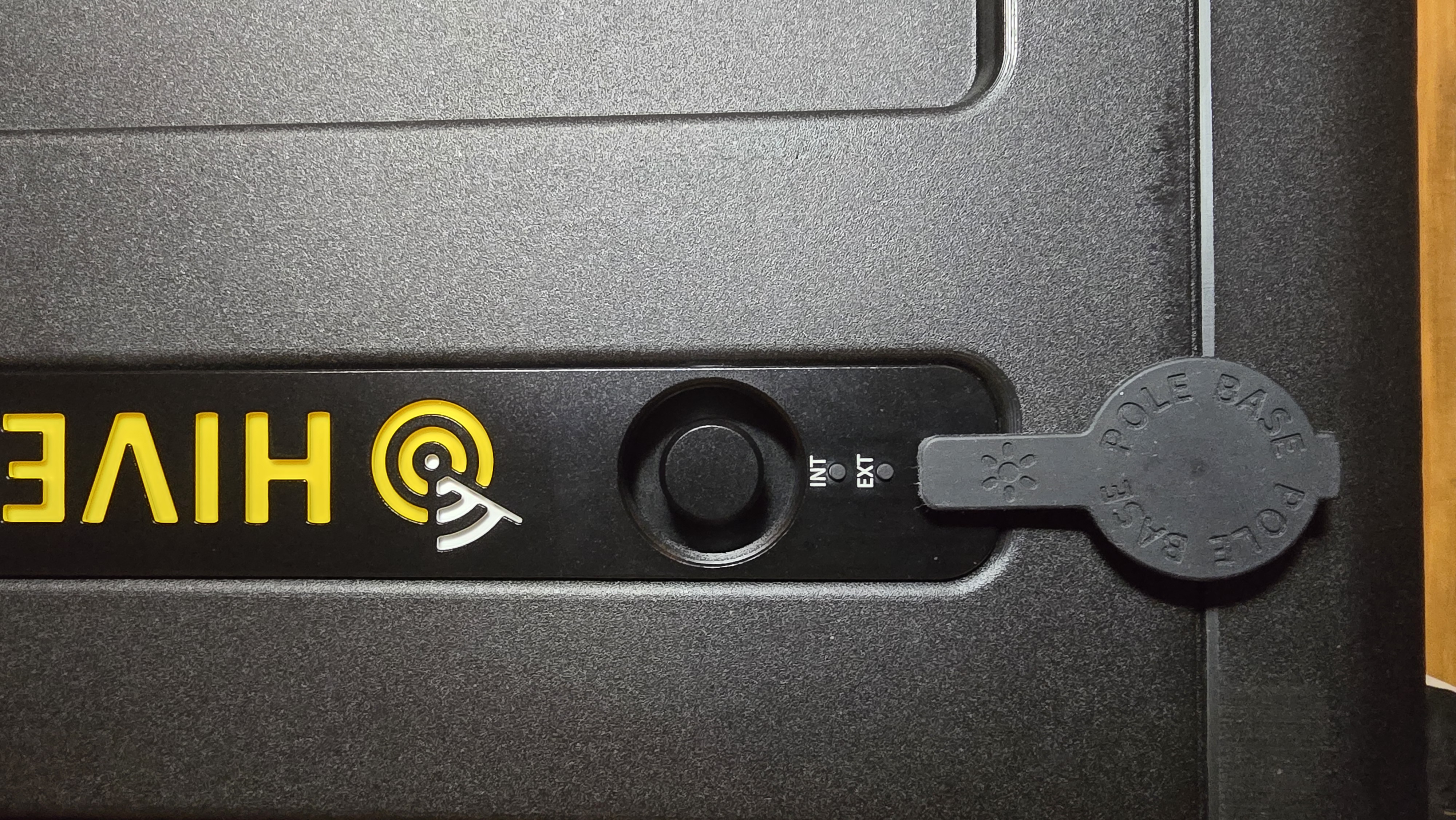
Step 2: Expose the Pole Mount
- Locate the pole mount on top of the deployed EDC (covered by a rubber protective cover)
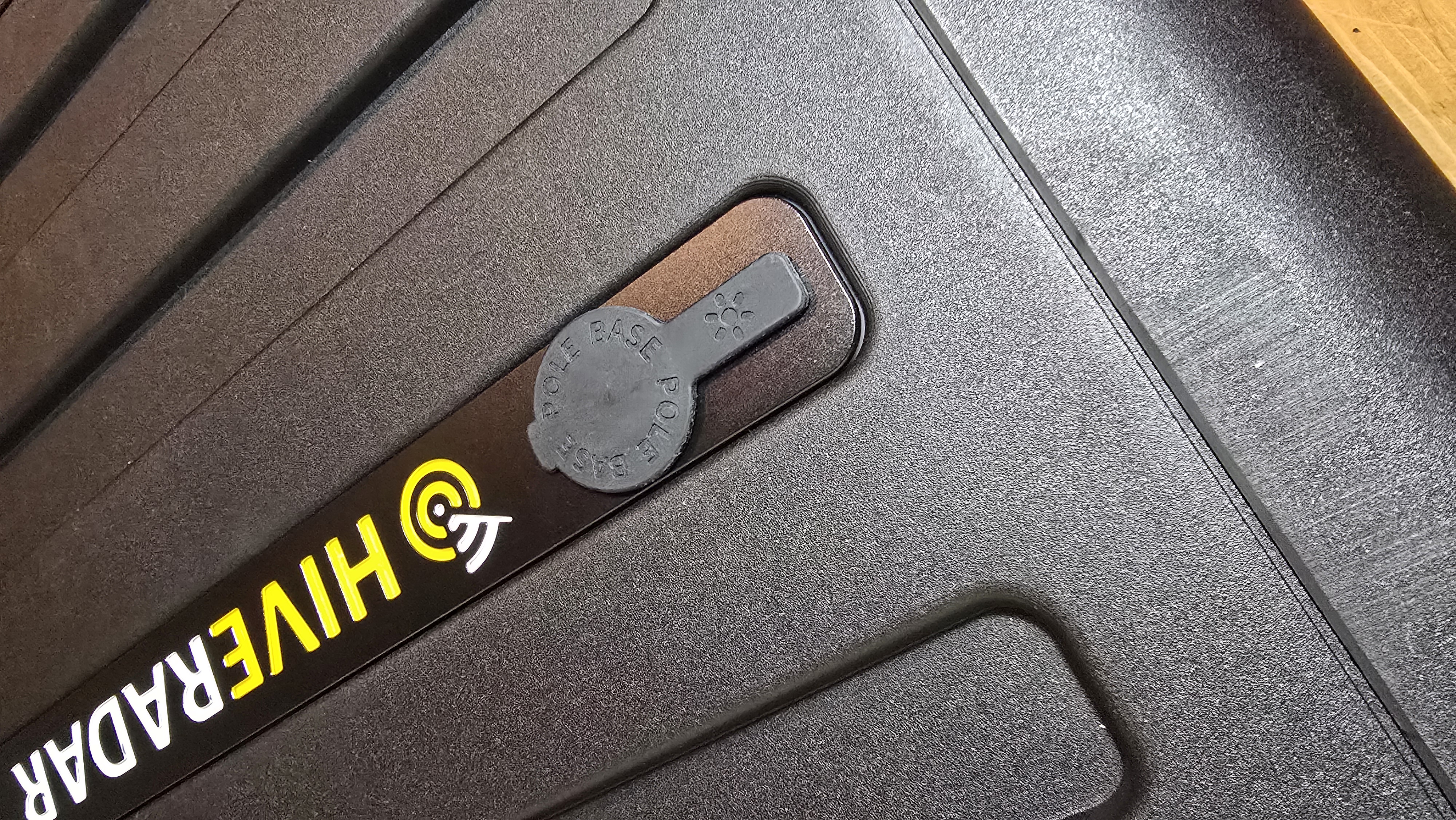
- Remove the rubber cover and set aside for later reinstallation
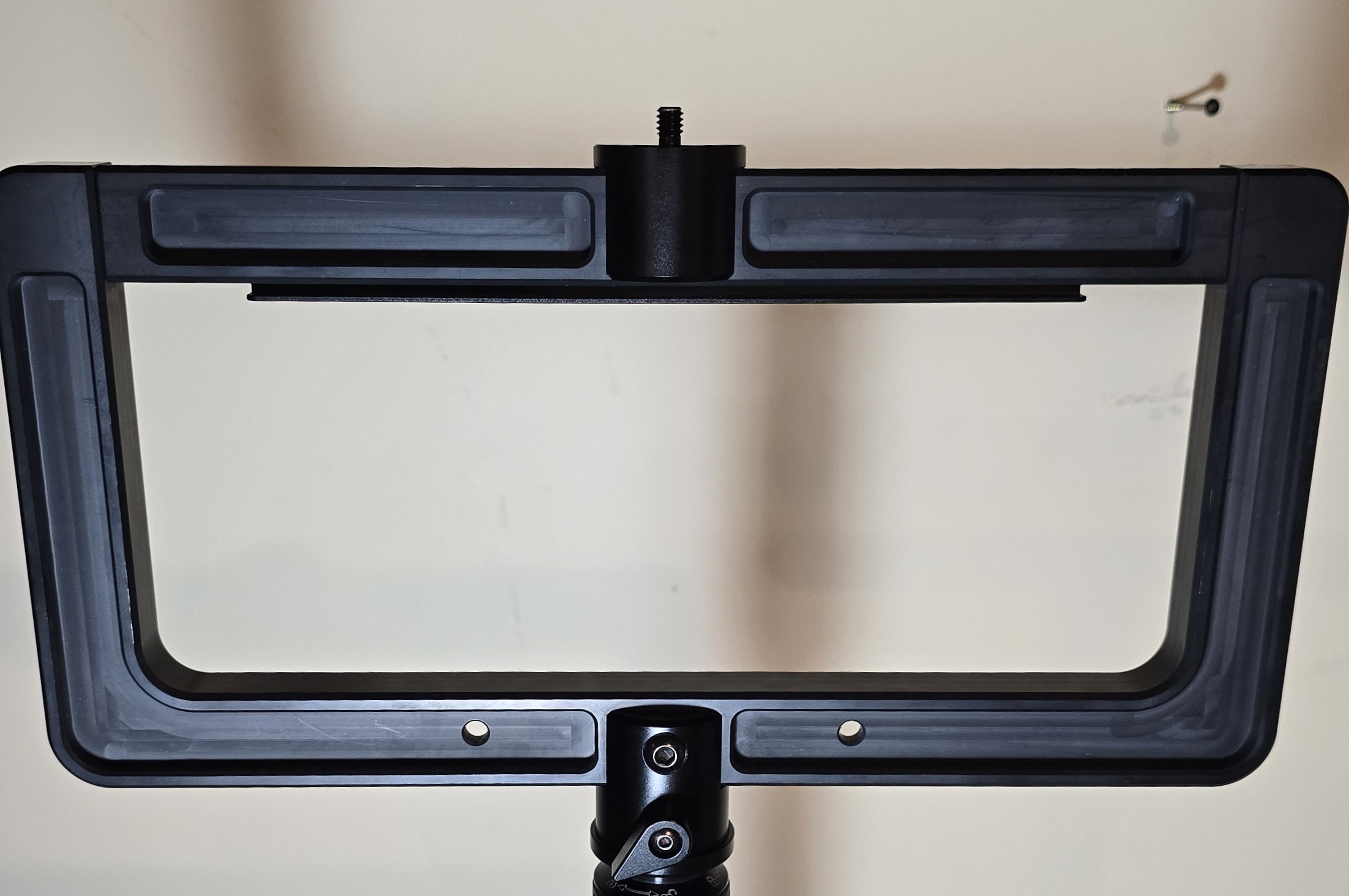
Step 3: Prepare the T-Bar Bracket
- Retrieve the T-bar bracket from the top storage shelf
- Identify the T-bar components:
- T-bar plate for mounting
- Pole attachment mechanism
- Orientation knob (for adjusting angle)
⚠️ Important: The orientation knob should only be loosened slightly - never completely unscrew it.
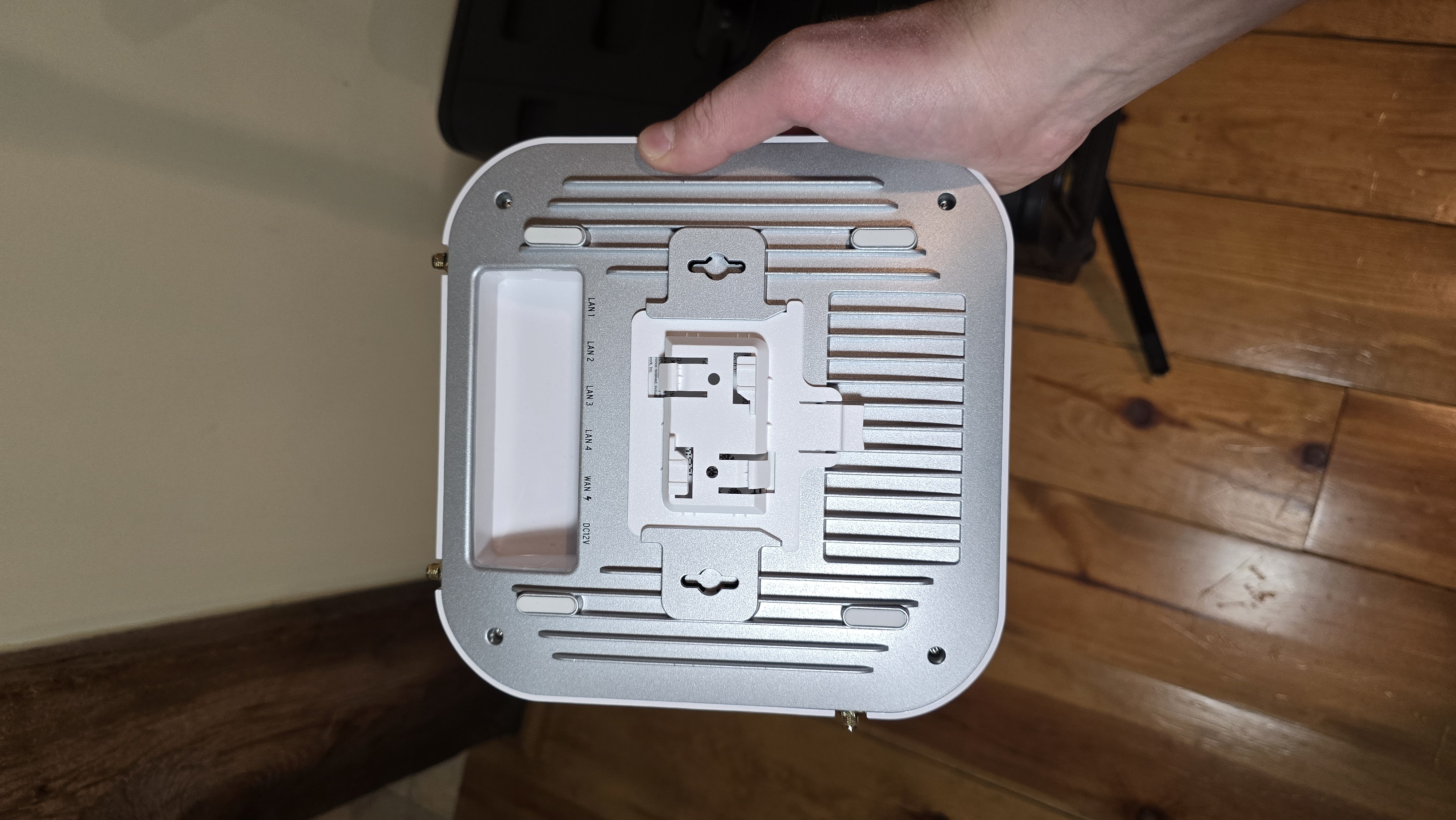
Step 4: Attach Gateway to T-Bar Bracket
For Mako 5600 Gateway:
-
Attach the T-bar adapter to the Mako gateway
- Provided by default and stored in accessory pouch
-
Mount the Mako gateway to the bracket
- Align and attach the gateway with the mounting bracket
- Make sure it is secured
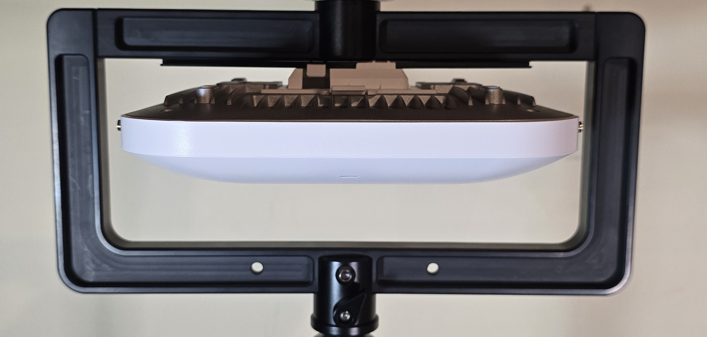
-
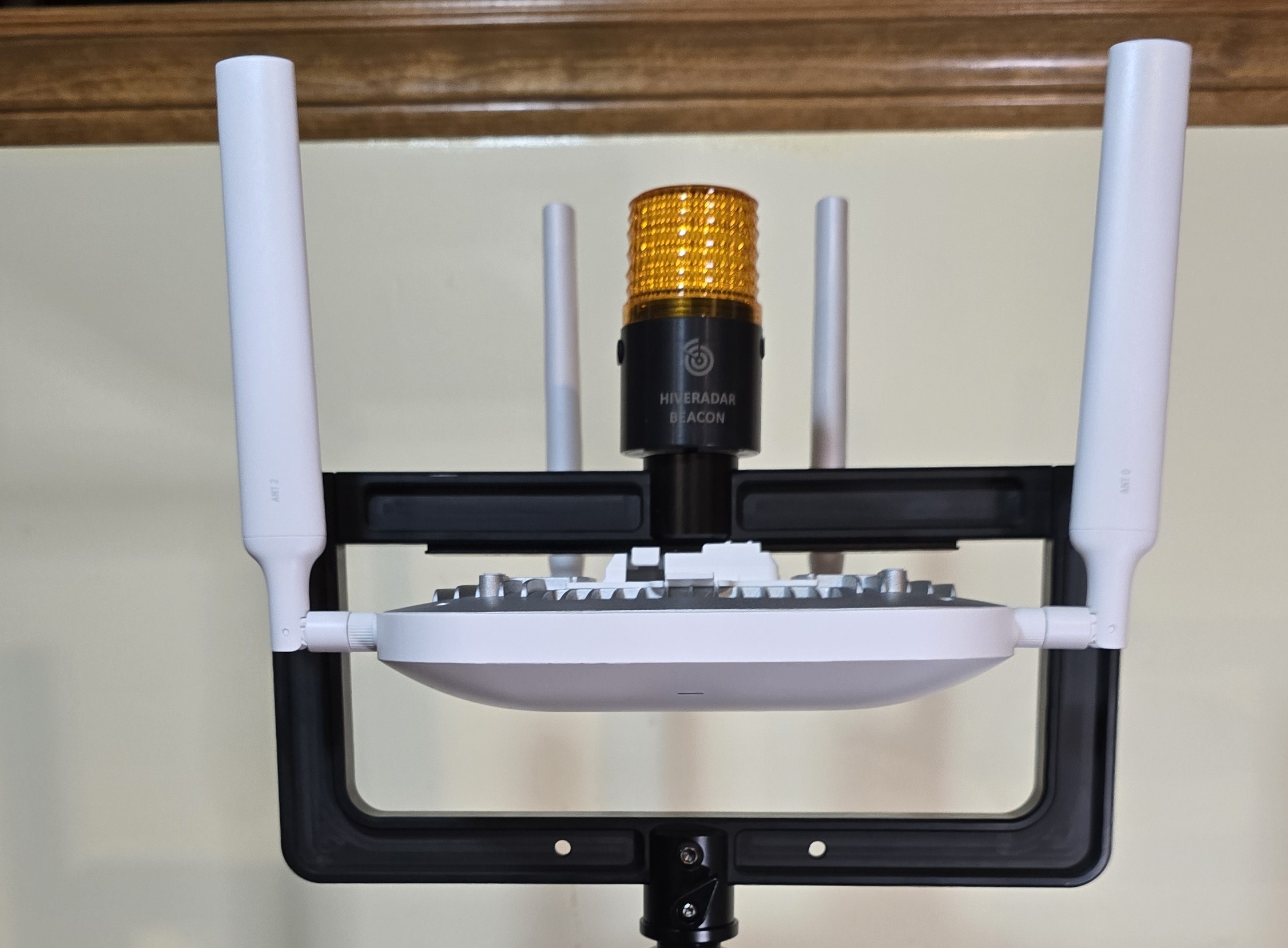
Install antennas
- Install antennas by using the corresponding number on the antenna and the gateway port
For Other Gateways or Access Points:
-
Attach device-specific mounting bracket to T-bar (if required)
-
Mount your gateway or AP to the bracket
- Follow manufacturer mounting instructions
- Ensure secure attachment to T-bar bracket
- Consider weight distribution
Optional: Install HiveRadar Beacon
The HiveRadar Beacon provides visual identification of the EDC location.
- Retrieve beacon from top storage shelf
- Mount beacon on top of T-bar bracket using the attachment mechanism
- Enable visual blinking (use the button on the side of the beacon)
Step 5: Attach T-Bar to Pole
-
Position the T-bar bracket on the carbon fiber pole
- Slide the T-bar bar mechanism onto the pole
-
Screw the T-bar clockwise onto the pole
- Do NOT fully tighten yet
- Leave slightly loose for orientation adjustment
-
Orient the T-bar bracket
- Loosen the orientation knob slightly (not fully)
- Rotate the T-bar to desired angle
- Tighten the orientation knob to lock position

⚠️ Warning: Never over-loosen the orientation knob - it should only move slightly to allow rotation.
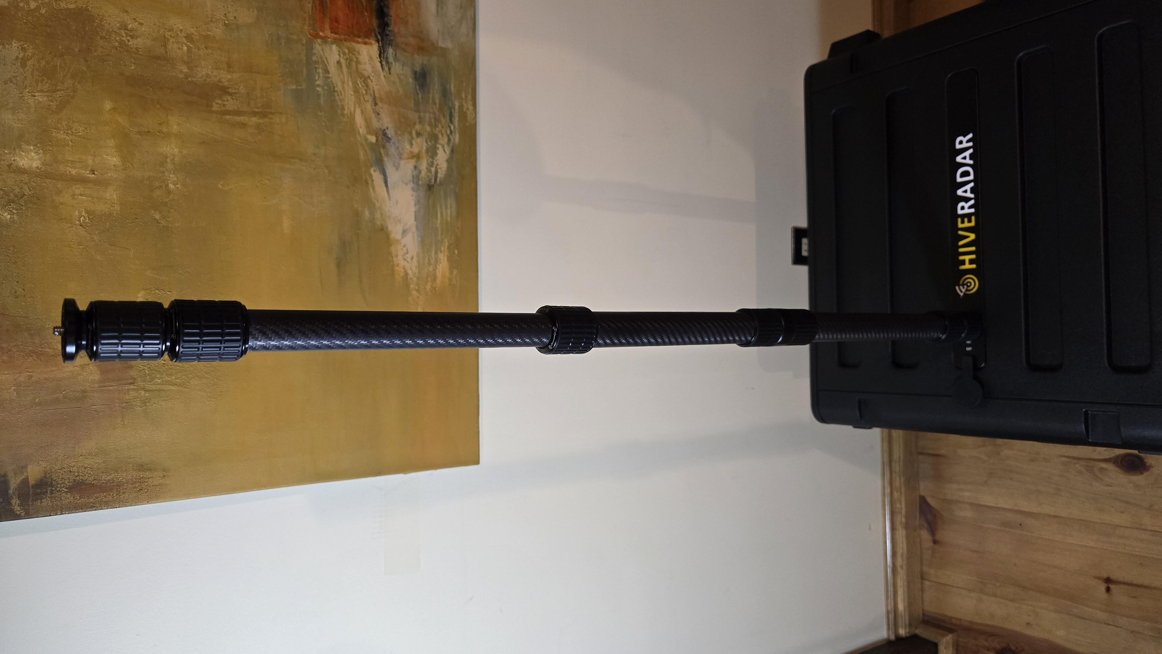
Step 6: Mount Pole to EDC
-
Check if pole needs extension
- You can either directly mount the 3 section telescoping pole or also use the carbon fiber pole extension that is stored in one of the lids
- If using only the 3 section pole, please make sure to extend the bottom section before attempting to screw the pole into the EDC
-
Screw the pole into the EDC pole mount
- Clockwise rotation
- If using extension pole, connect extension first, then mount to EDC
-
Tighten securely
- Ensure pole is stable and secure
Image below is using the carbon fiber pole extension without the T-bar bracket as an example of mounting the pole to the EDC hardcase.
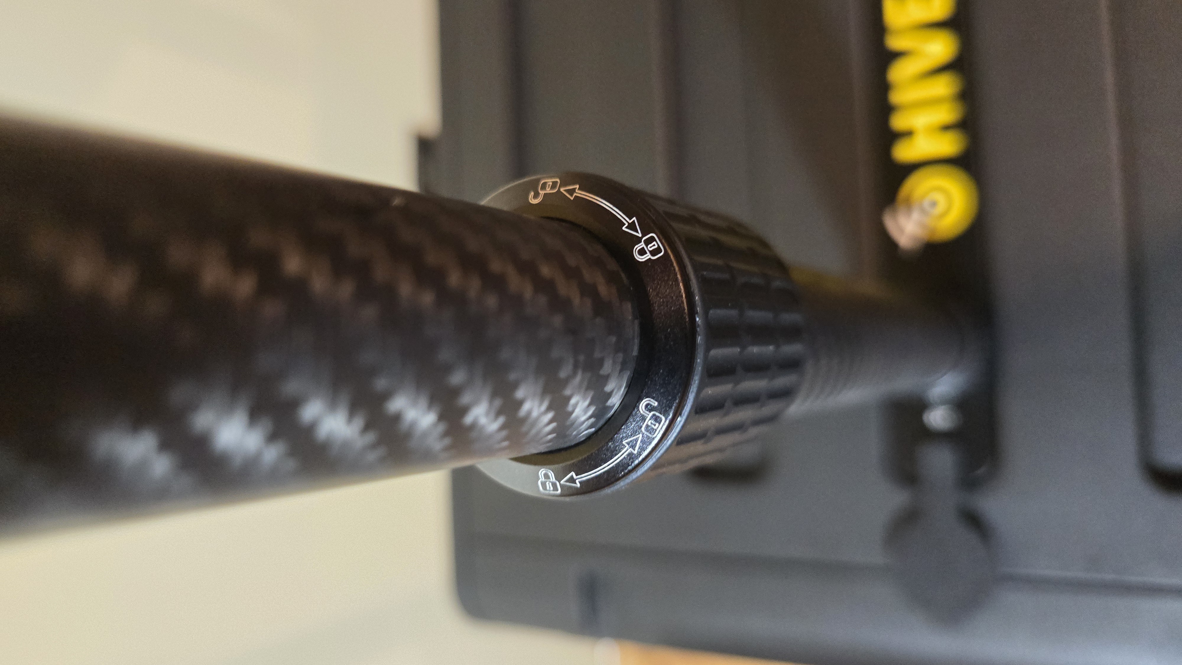
Note: Extension/retraction symbols are printed on the pole itself for reference.
Step 7: Adjust Pole Height
- Extend the telescoping pole to desired height
- Follow the lock symbols on the poles
- Typically twist to unlock, extend/retract, twist to lock
- Ensure all segments are locked before releasing
Step 8: Connect Cables
Connect Mako 5600 Gateway
Cable Requirements:
- 2× Ethernet cables (included in EDC accessory kit)
- Connect cables to the Mako Gateway
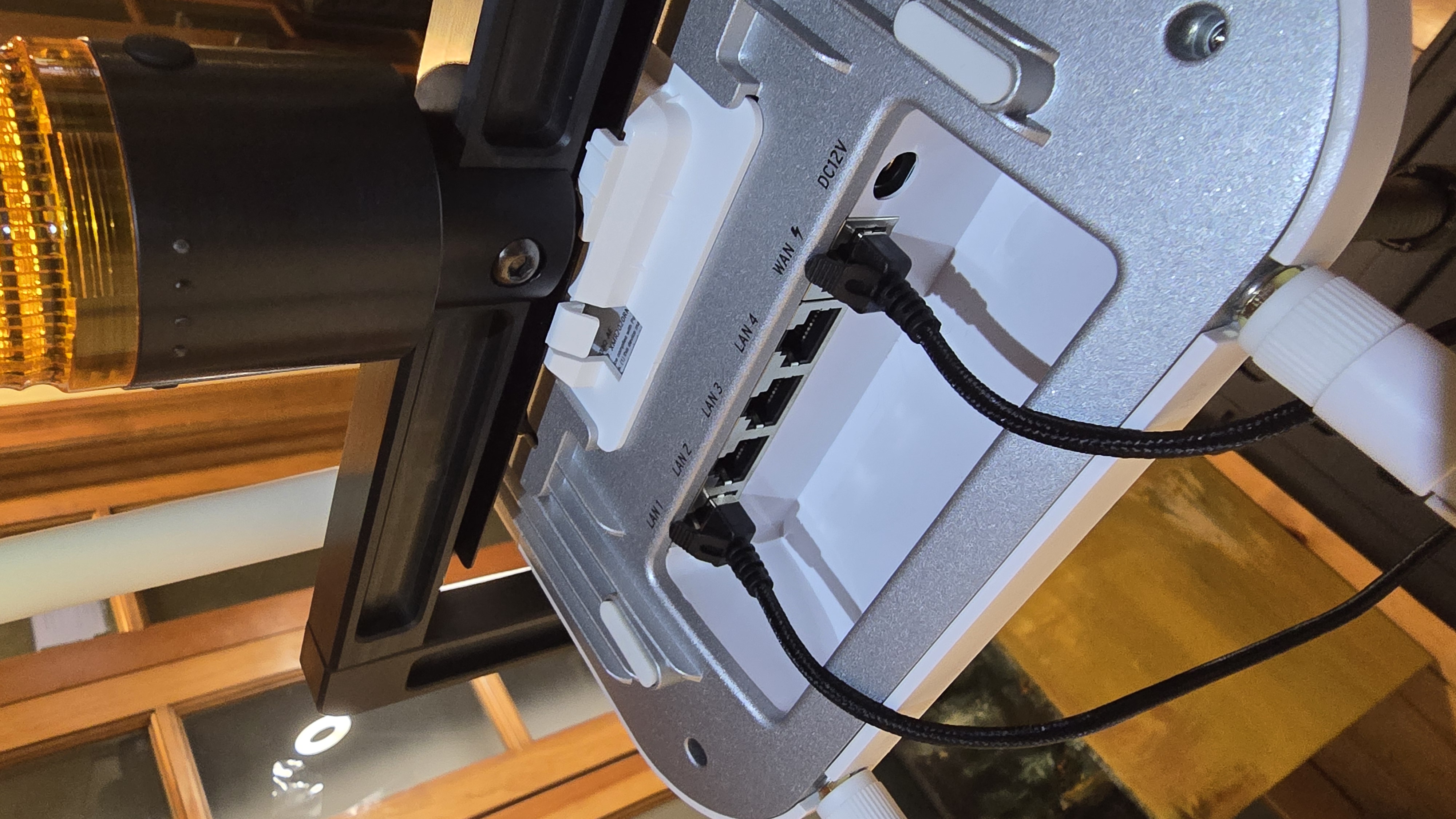
- Take the two Ethernet cables and plug them into the Mako Gateway:
- Connect the first cable to the WAN port
- Connect the second cable to the LAN port
- Take the two Ethernet cables and plug them into the Mako Gateway:
-
Route and secure cables
- Route both cables down the pole towards the EDC
- Cable Management: Bundle the cables together using velcro straps; ensure the run is tight and looks neat (avoid loose hanging loops)
-
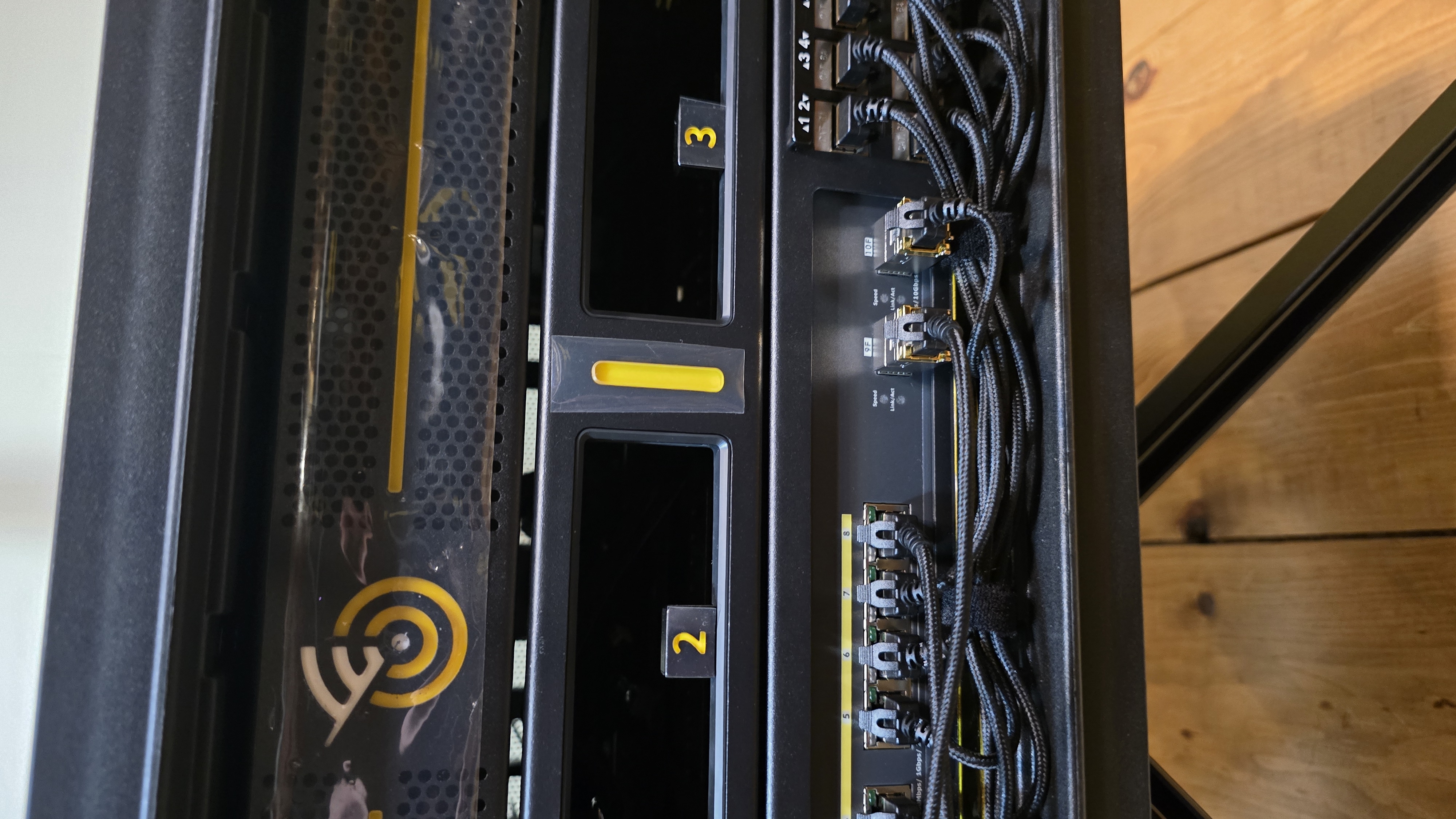
Connect cables to the Switch
- Identify which cable corresponds to WAN and which to LAN, then connect them to the Switch:
- WAN Cable (Power): Connect to Switch Port 8 (RJ45 port)
- ⚠️ Important: This connection provides PoE power only. Network access on this port must be disabled or VLAN isolated (Mako limitation)
- LAN Cable (Data): Connect to Switch Port 9 (SFP+ copper transceiver)
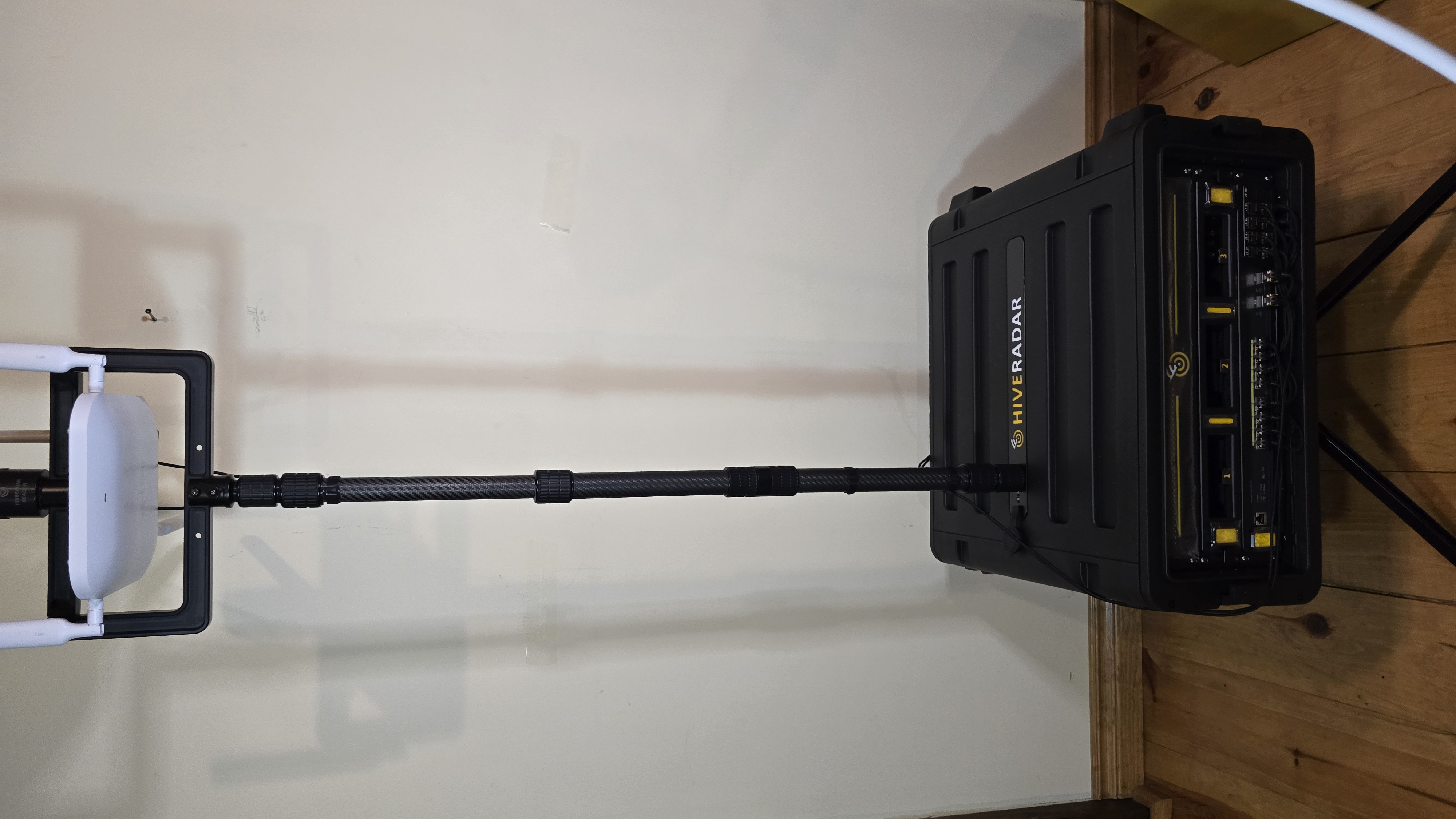
Fully deployed:
For Other Gateways or Access Points:
Typical Configuration:
- Single Ethernet cable for data and PoE power
- Connect to available switch port (e.g., Port 8)
- Consult device documentation for port requirements
Cable Management:
- Route cables down the carbon fiber pole
- Leave slight slack at top to prevent strain
- Protect cables from pinching when retracting pole
Safety Notes
Pole Stability:
- Ensure pole is securely mounted before extending
- Do not extend pole in high winds
- Consider retracting pole during transport
T-Bar Orientation Knob:
- Never fully loosen the orientation knob
- Loosen only enough to allow rotation
- Over-loosening may cause parts to separate
Weight Considerations:
- Keep gateway weight reasonable
- Heavy equipment may affect stability
- Consider retracting pole in extreme weather
Cable Management:
- Secure cables along pole to prevent snagging
- Leave some slack for pole extension/retraction
- Protect cable connections from weather if deployed outdoors
Troubleshooting
Pole won't screw into mount:
- Check thread alignment
- Ensure rubber cover is fully removed
- Try slight rotation while applying pressure
T-bar won't stay oriented:
- Tighten orientation knob more
- Check that knob hasn't been over-loosened
- Ensure T-bar is properly seated on pole
Gateway not getting power:
- Verify cable connected to correct switch port
- Check that port has PoE enabled on switch
- Verify switch is powered on
Disassembly and Storage
To remove the gateway and pole:
- Disconnect cables from gateway
- Retract telescoping pole to shortest position
- Unscrew pole from EDC mount (counterclockwise)
- Remove gateway from T-bar if desired
- Store components:
- Carbon fiber pole → top drawer
- Extension pole → work surface lid storage
- T-bar bracket → top storage shelf
- Gateway and antennas → secure storage
- Replace rubber cover on pole mount
What's Next?
After deploying the gateway:
👉 Positioning - Review clearance requirements with extended pole
👉 Component Locations - Reference guide for all EDC components
Continue to Part 4: Software Configuration for power and network setup.