NUC Installation
Step-by-step installation of Intel NUC Pro compute nodes in the EDC.
⏱️ Time Required: 60-90 minutes
Before You Begin
Prerequisites:
- Part 2: Physical Deployment completed
- Installation Overview reviewed
- Workspace prepared with ESD protection
- AC power disconnected from PDU
Tools needed:
- 4mm hex key (stored in top shelf compartment - same one used for transportation locks)
- ESD wrist strap (recommended)
- Flashlight (helpful for viewing tight spaces)
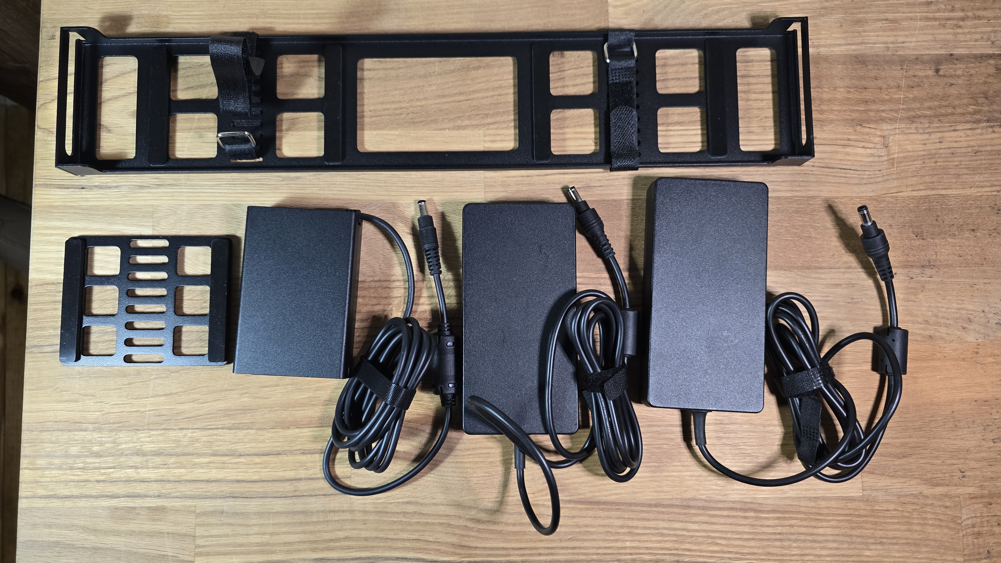
Components needed:
- 3× NUC PRO form factor compute nodes
- 3× Power supply units (PSUs) for each NUC
- Velcro straps for PSUs (included in EDC accessory pouch)
- PSU-to-PDU right-angle power cables (in accessory pouch or pre-installed on PDU)
- ESD protection equipment
[IMAGE: NUC installation components laid out - 3× NUCs, 3× PSUs, velcro straps, right-angle cables, hex key]
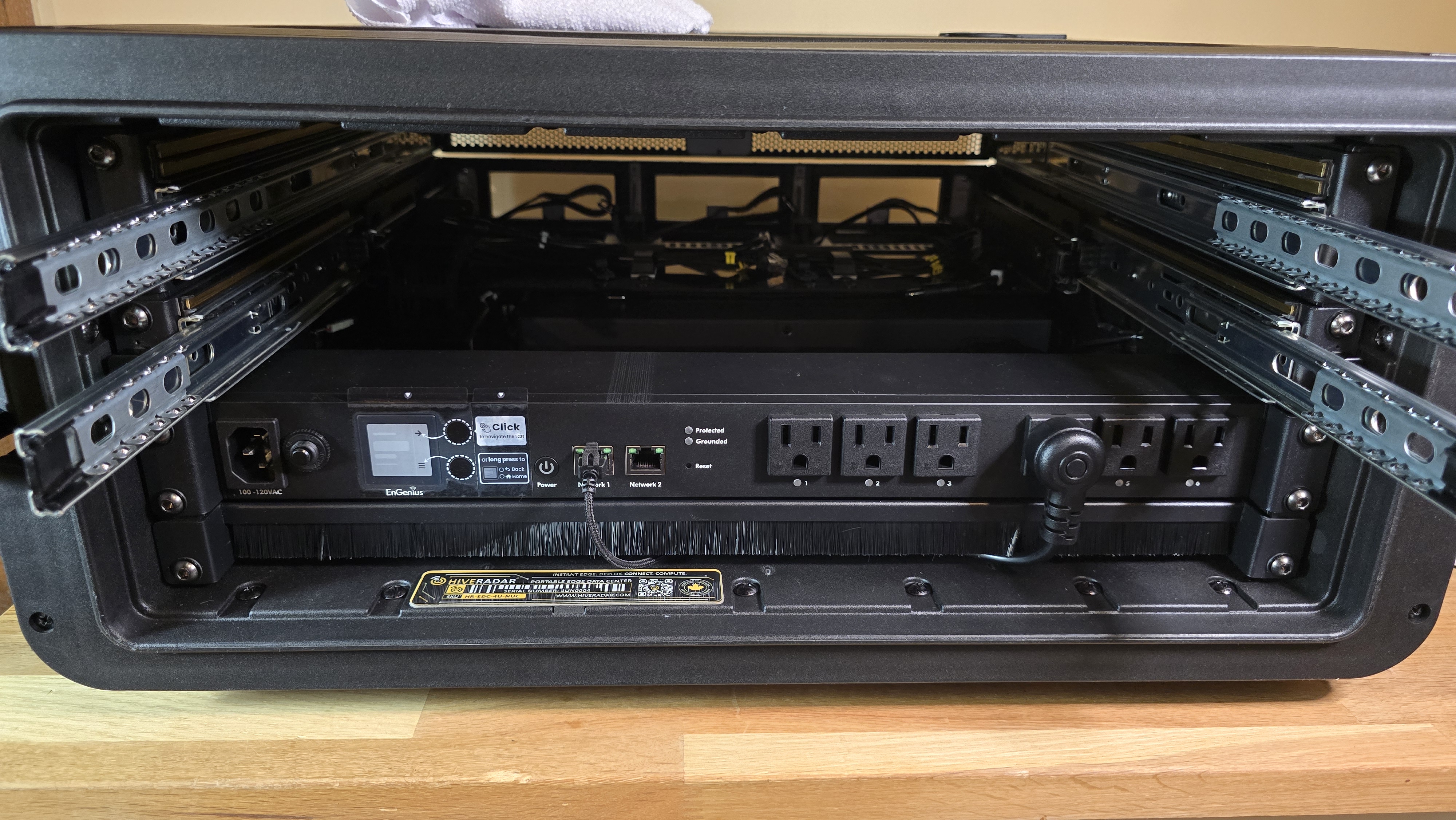
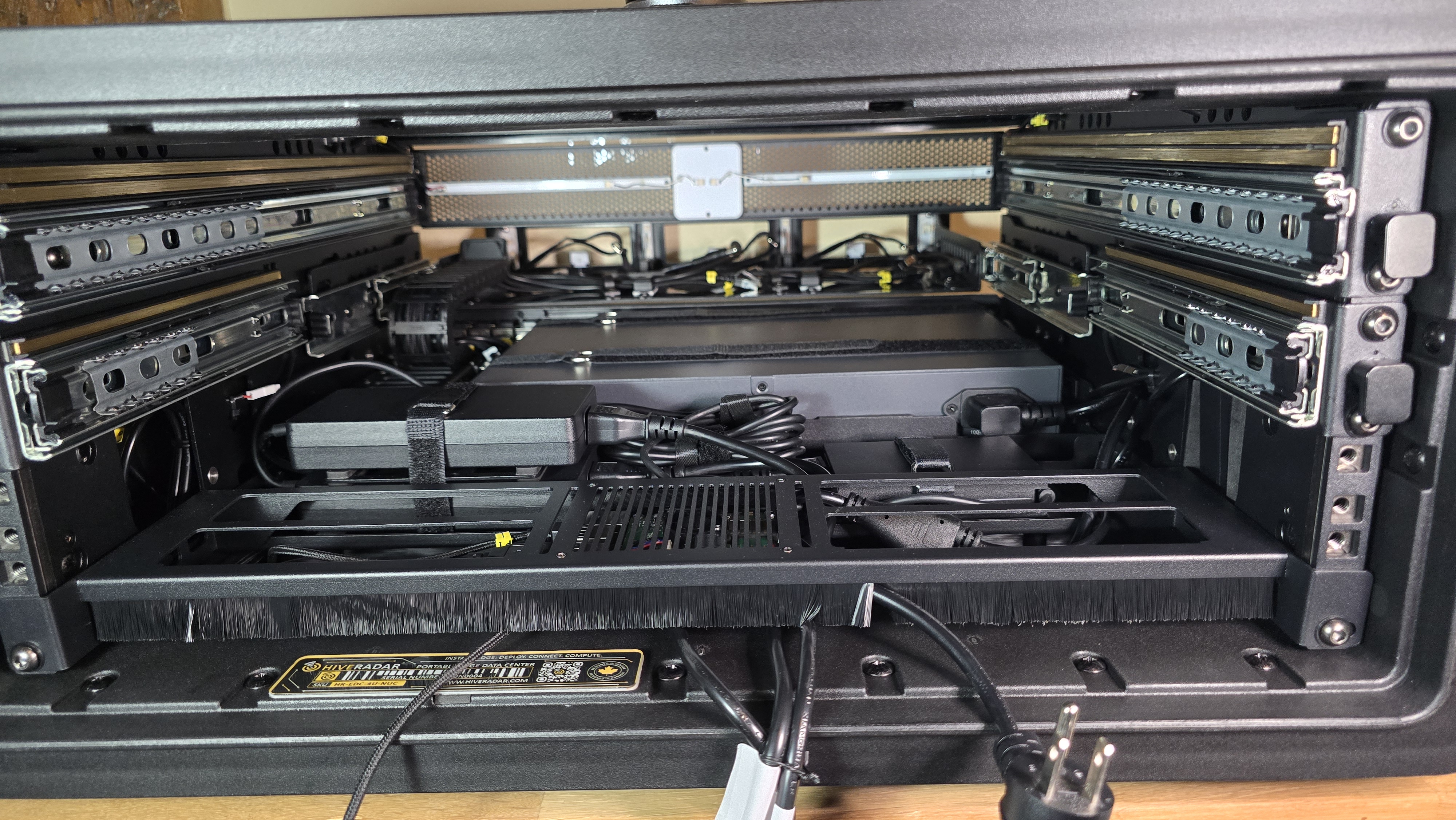
Step 1: Install Power Supply Units (PSUs)
Overview: The PSU mounting area is located between the PDU and switch on the rear panel. To access this area, you'll need to temporarily remove drawers,the PDU, and the brush panel below the PDU.
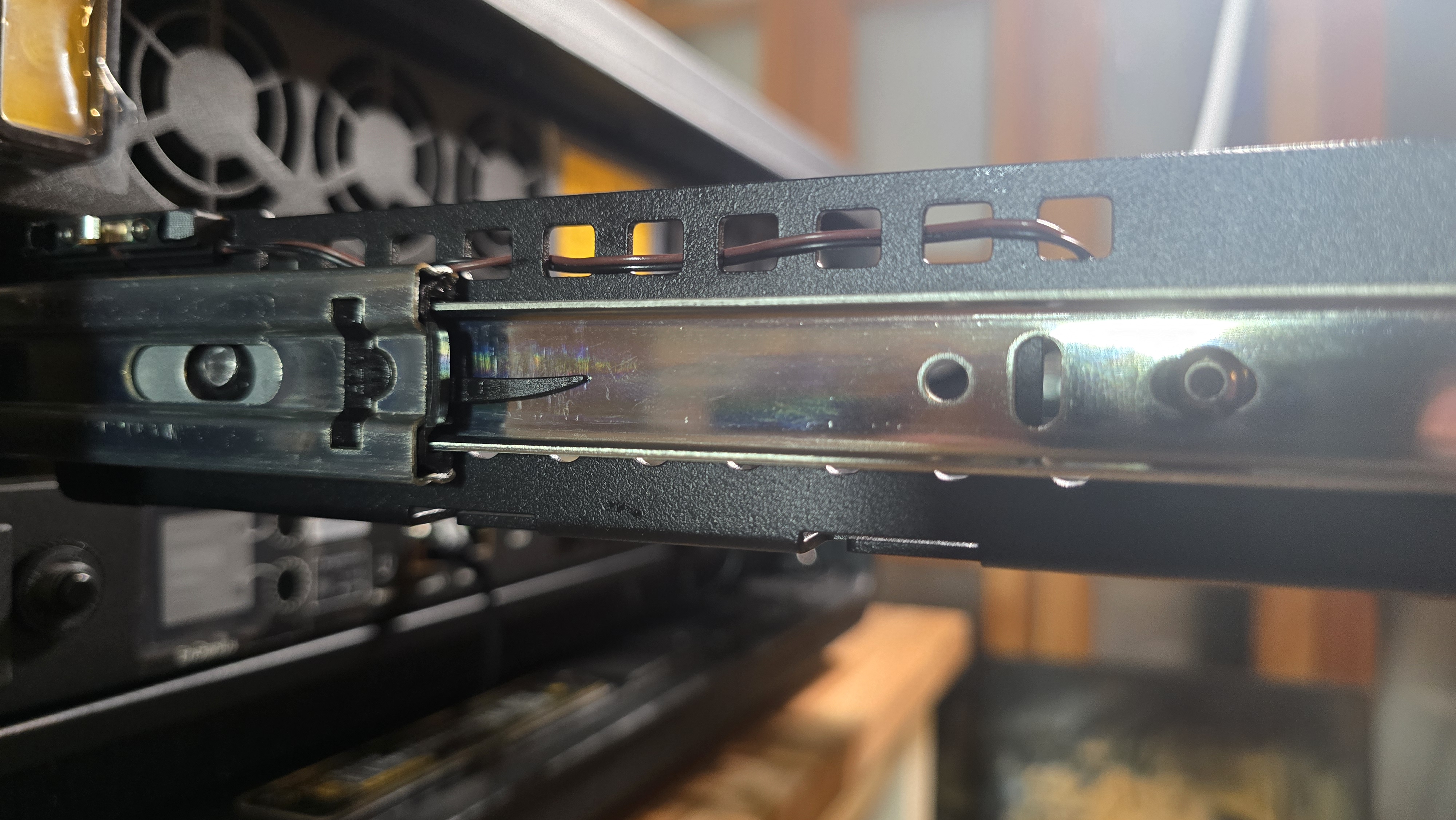
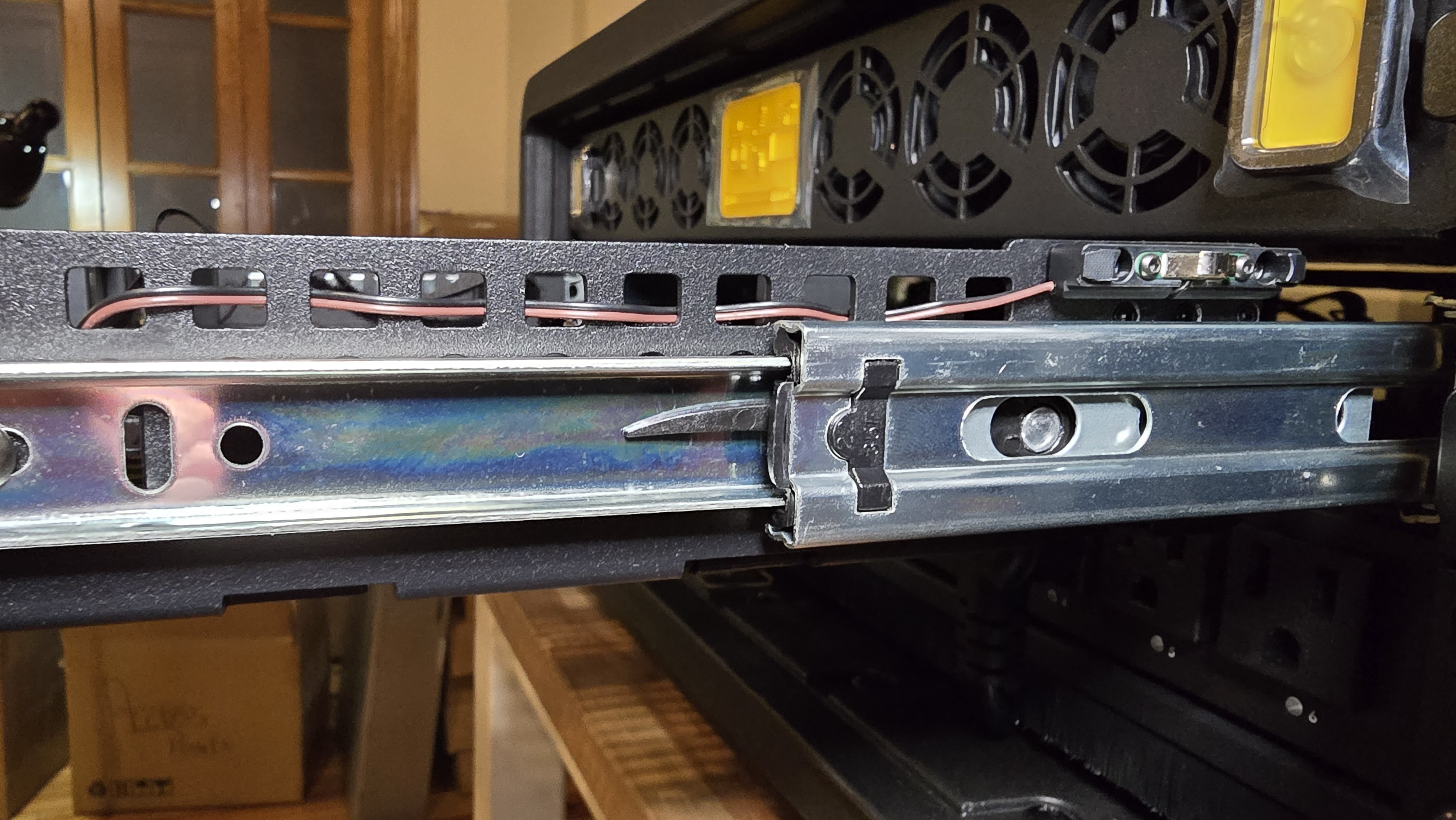
1.1: Remove Short-Depth Drawer (Middle Drawer)
- Extend drawer fully
- Pull top drawer out to its fully extended position
- Release drawer from rails
- Look at both sides of the drawer rails
- Locate plastic release tabs on each rail:
- Left side: Lift tab upward
- Right side: Press tab downward
- Tabs bend naturally in one direction only - do not force opposite direction
-
Remove drawer from rails
Method 1 (Recommended):
- Hold both release tabs engaged (left up, right down)
- Pull drawer straight toward you until it separates from rails
Method 2 (Alternative):
- Support drawer weight with one hand
- Release one side: Hold tab and slide the EDC-side rail section inward to disengage
- Keep drawer supported on remaining engaged side
- Release second side: Hold tab and slide that rail section inward
- Carefully pull the drawer away once both sides are disengaged
Important: Always support drawer weight to prevent dropping when rails disengage
- Set drawer aside in safe location
1.2: Remove Full-Depth Drawer (Top Drawer)
- Repeat removal process
- Follow the same steps as full-depth drawer removal:
- Extend drawer fully
- Press release tabs (left up, right down)
- Pull drawer out and set aside
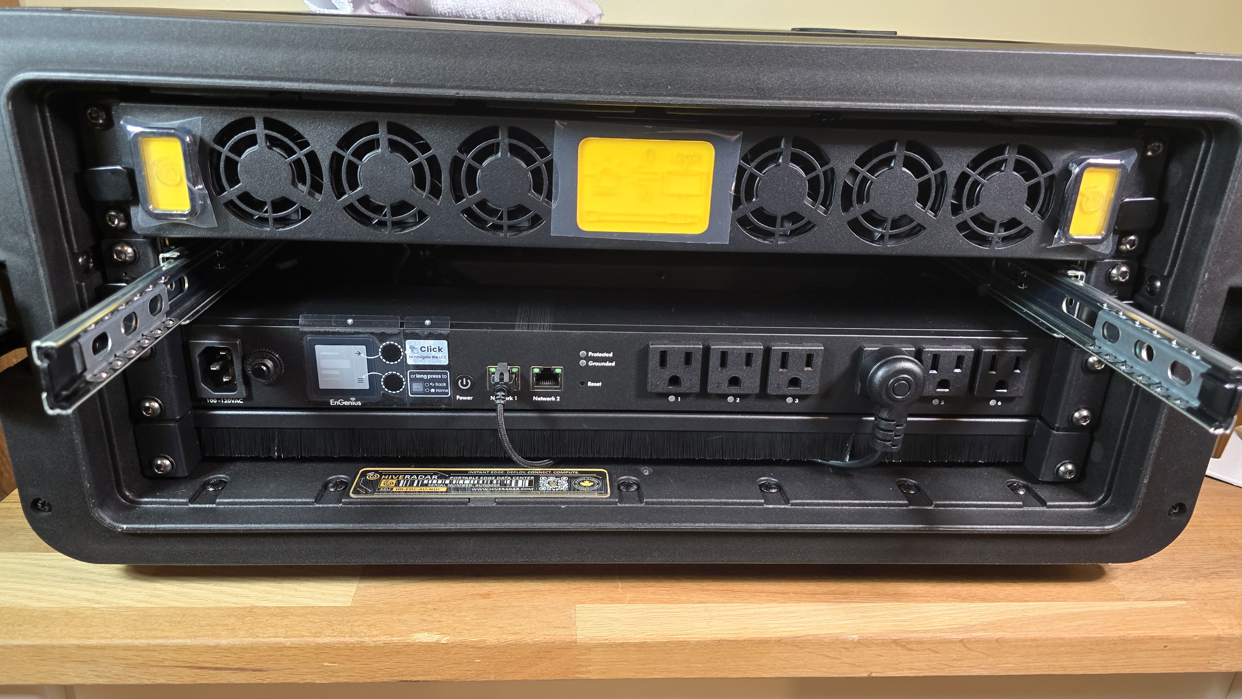
1.3: Remove the PDU and the brush panel
-
Disconnect network and power cables from PDU
- Unplug all power cables currently connected to PDU outlets
- Unplug the network cable connected to 'Network 1' RJ45 port
- Recommended: Label each power cable with its outlet number before disconnecting
- This ensures correct reconnection later per power diagram
-
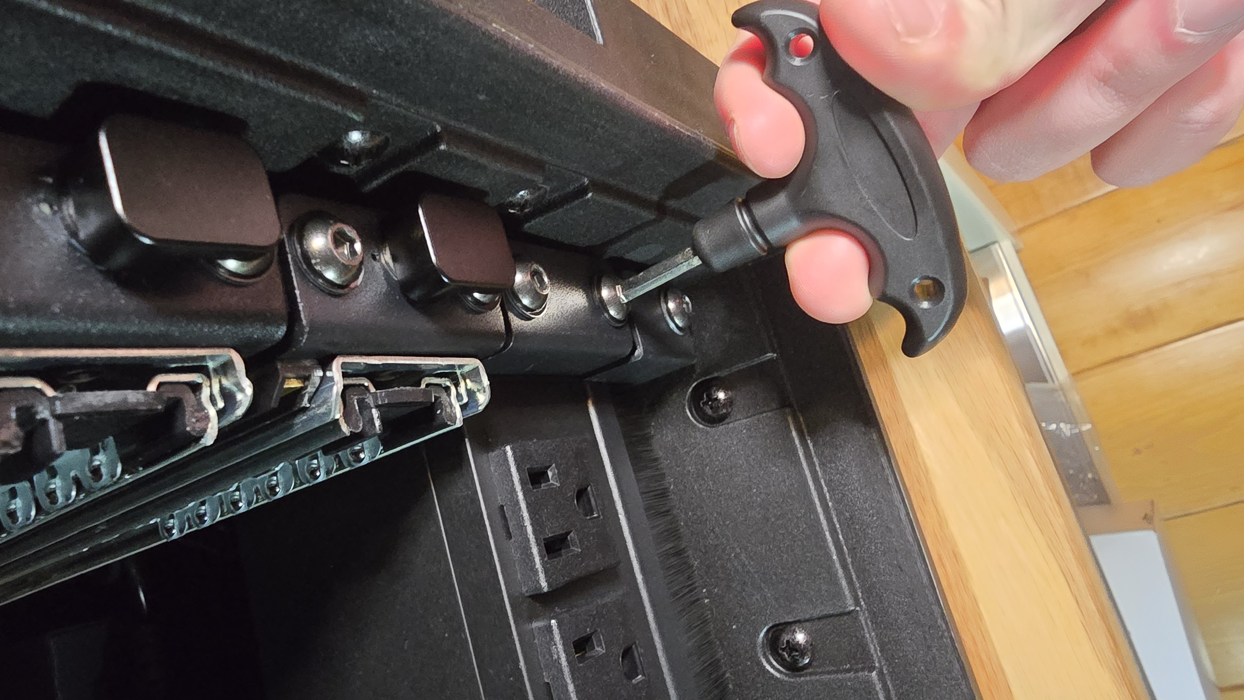
Remove PDU mounting screws
- Use 4mm hex key (stored in top shelf compartment)
- Unscrew 4× hex bolts on sides of PDU (2 per side)
- Set screws aside in safe location
- Remove the PDU
- Carefully lift the PDU and put it aside
-
Remove brush panel screws
- Unscrew 2× hex bolts on sides of brush panel (1 per side)
- Brush panel is located below the PDU location
-
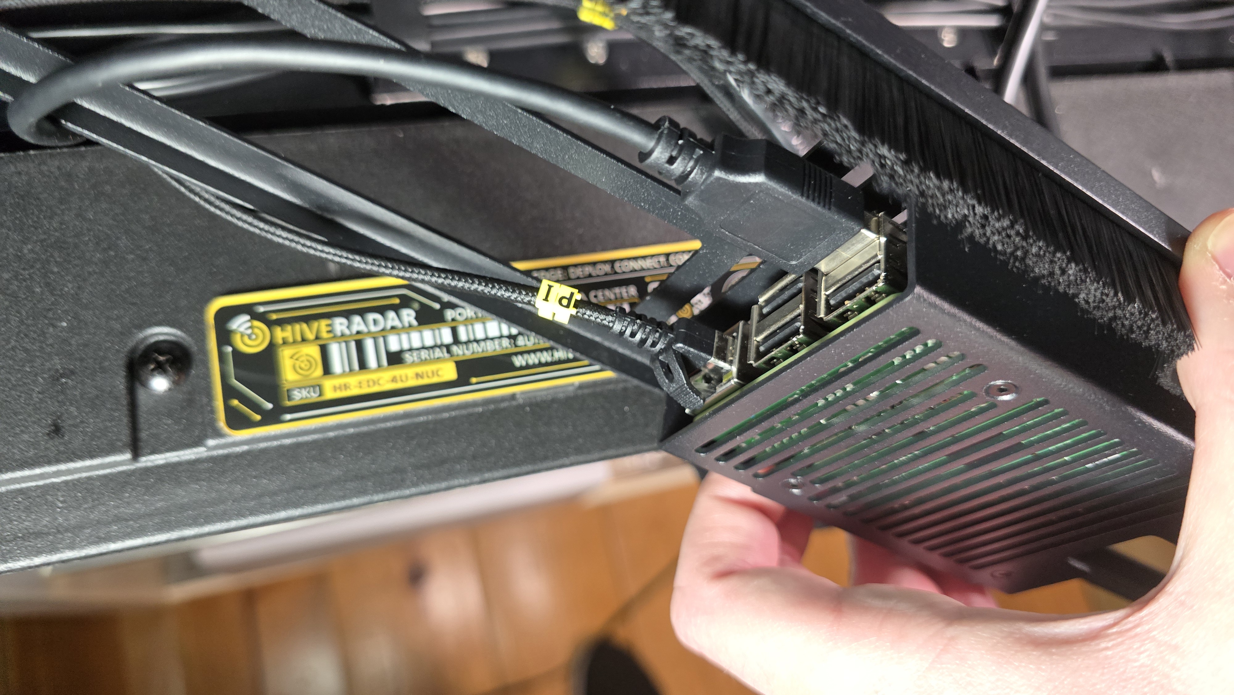
Unplug the USB and Ethernet cable from the IoT device
- Carefully remove the cables from the ports on the device
- Note: Brush panel houses IoT device with 2 cables:
- Ethernet cable (to keystone panel - pre-wired)
- USB cable (to keystone panel - pre-wired)
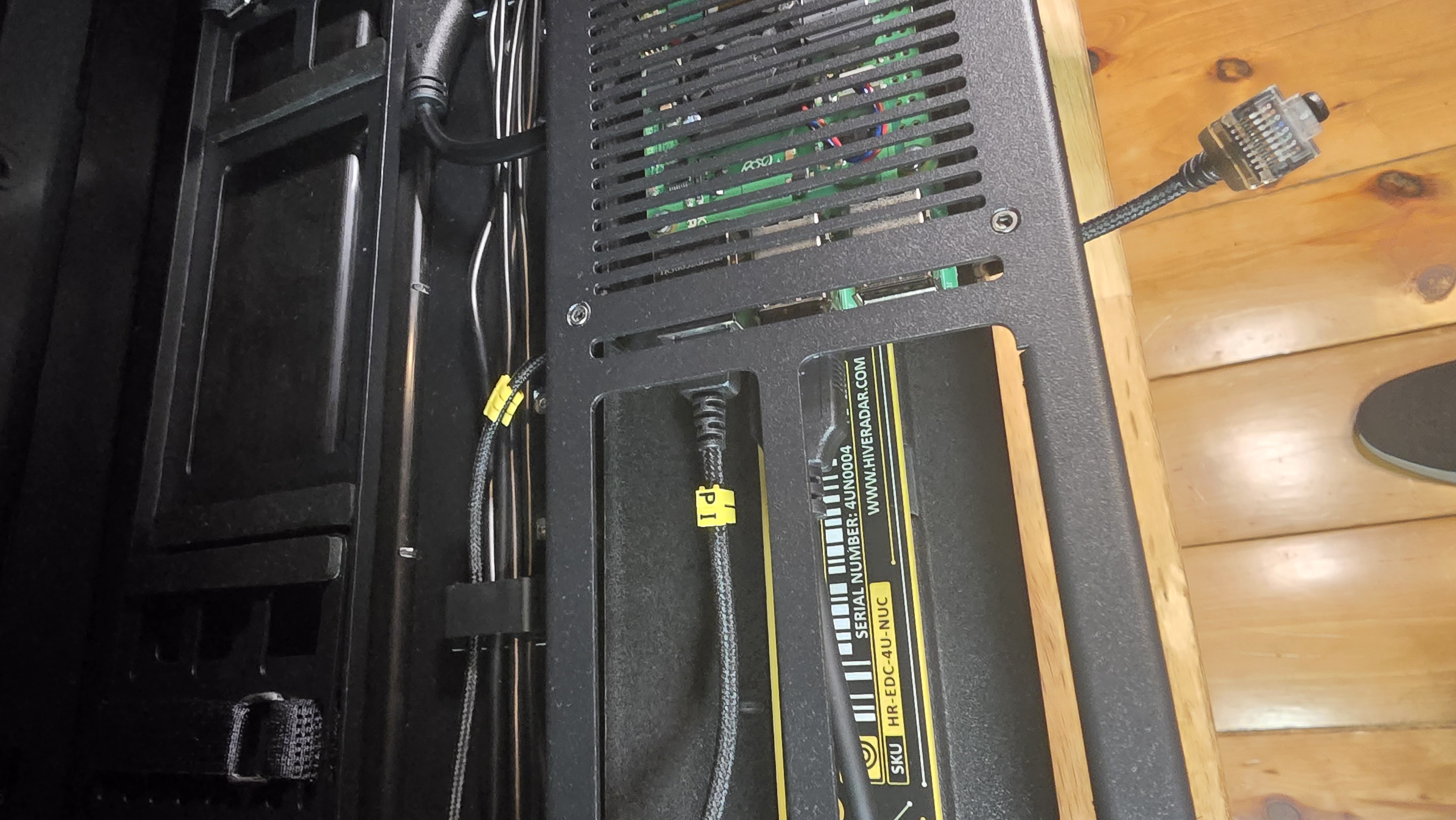
- Remove the brush panel assembly
- Carefully lift the brush panel assembly and put it aside
[IMAGE: PDU and brush panel being lifted away - IoT device cables visible]
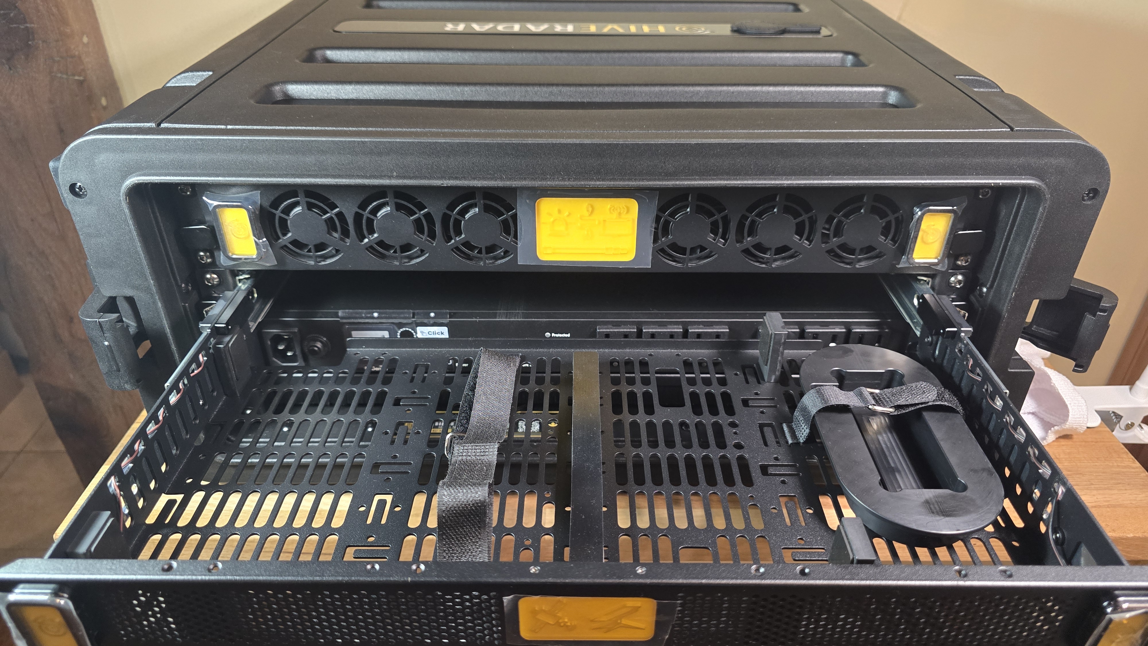
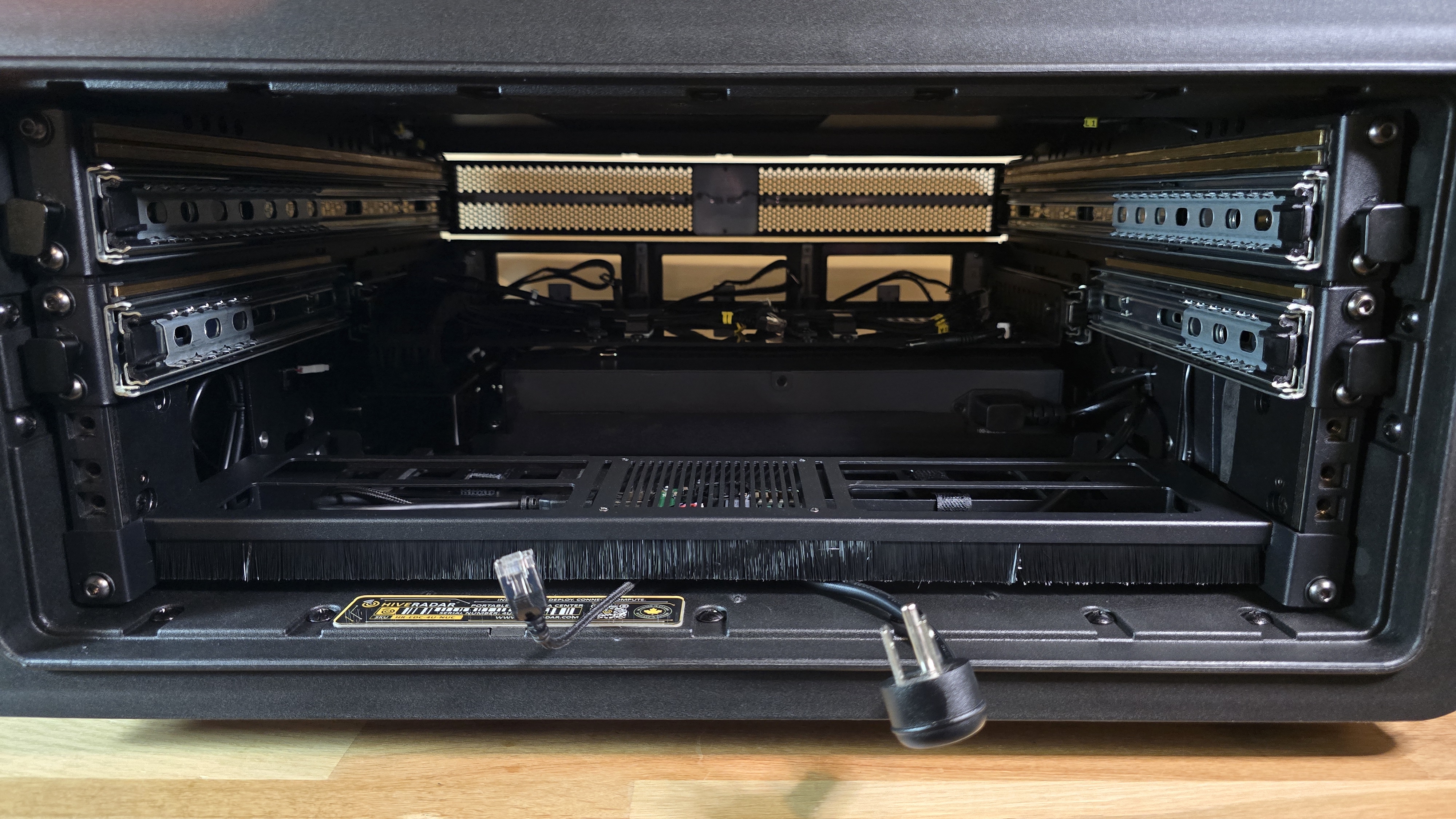
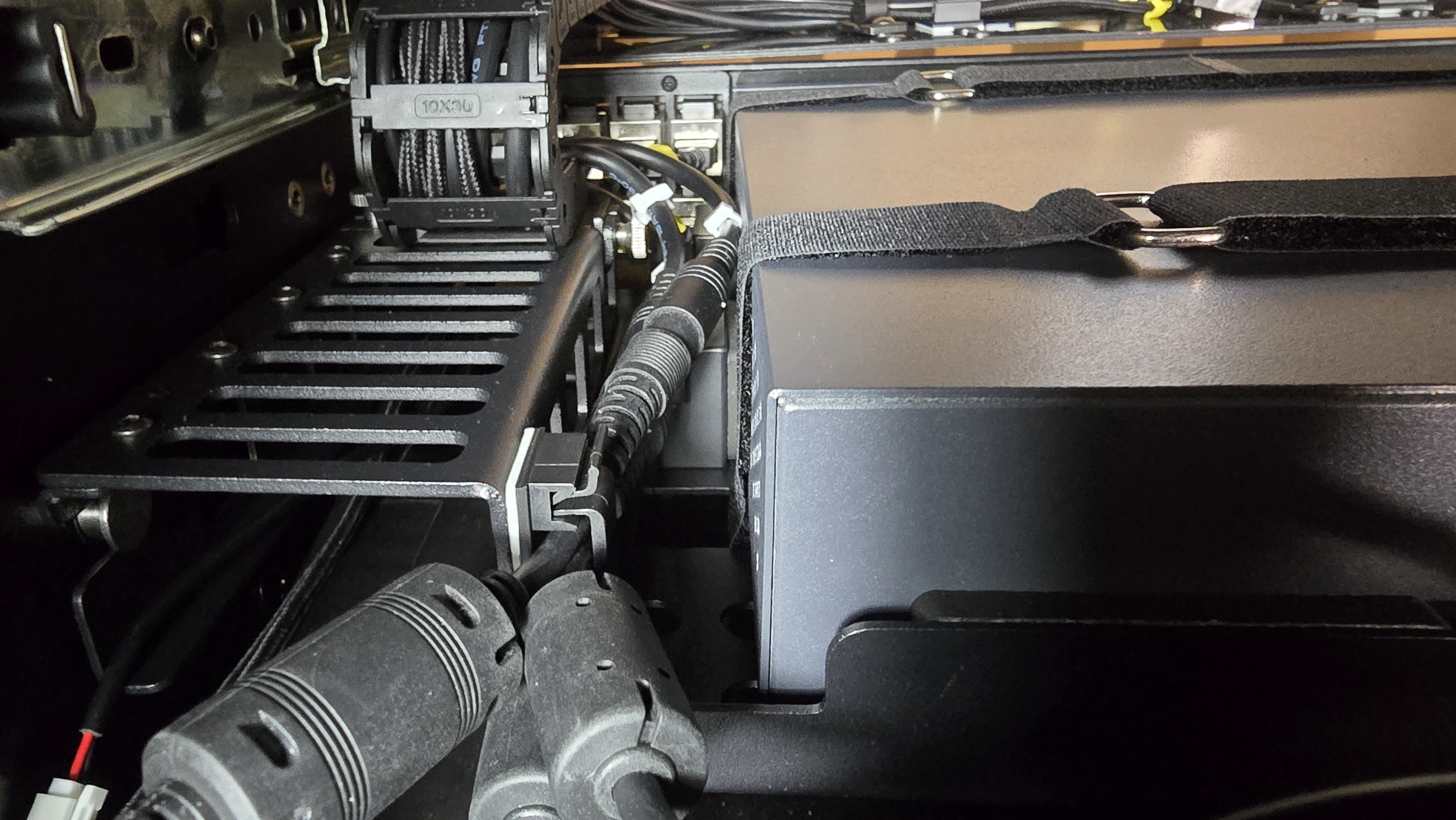
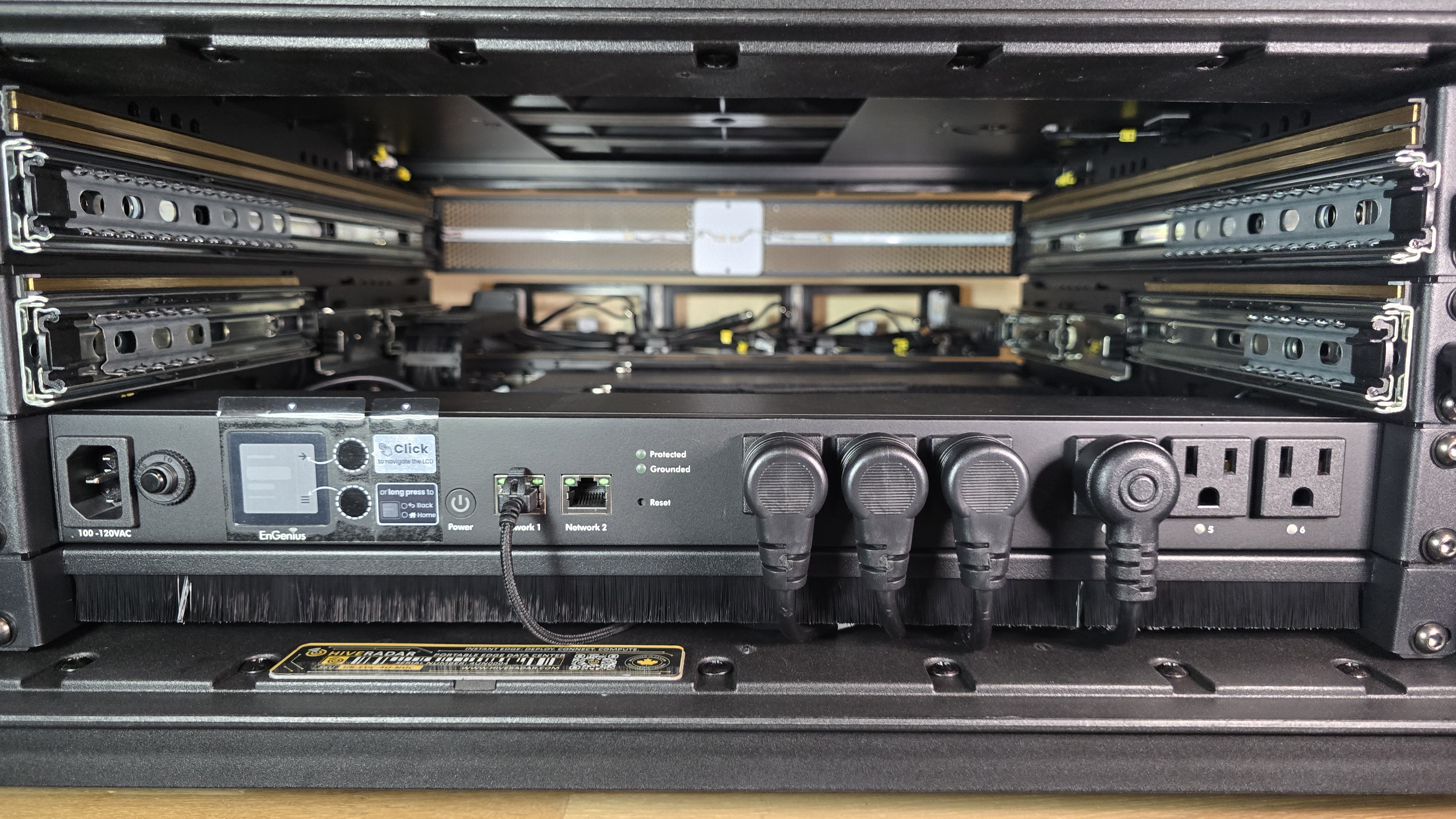
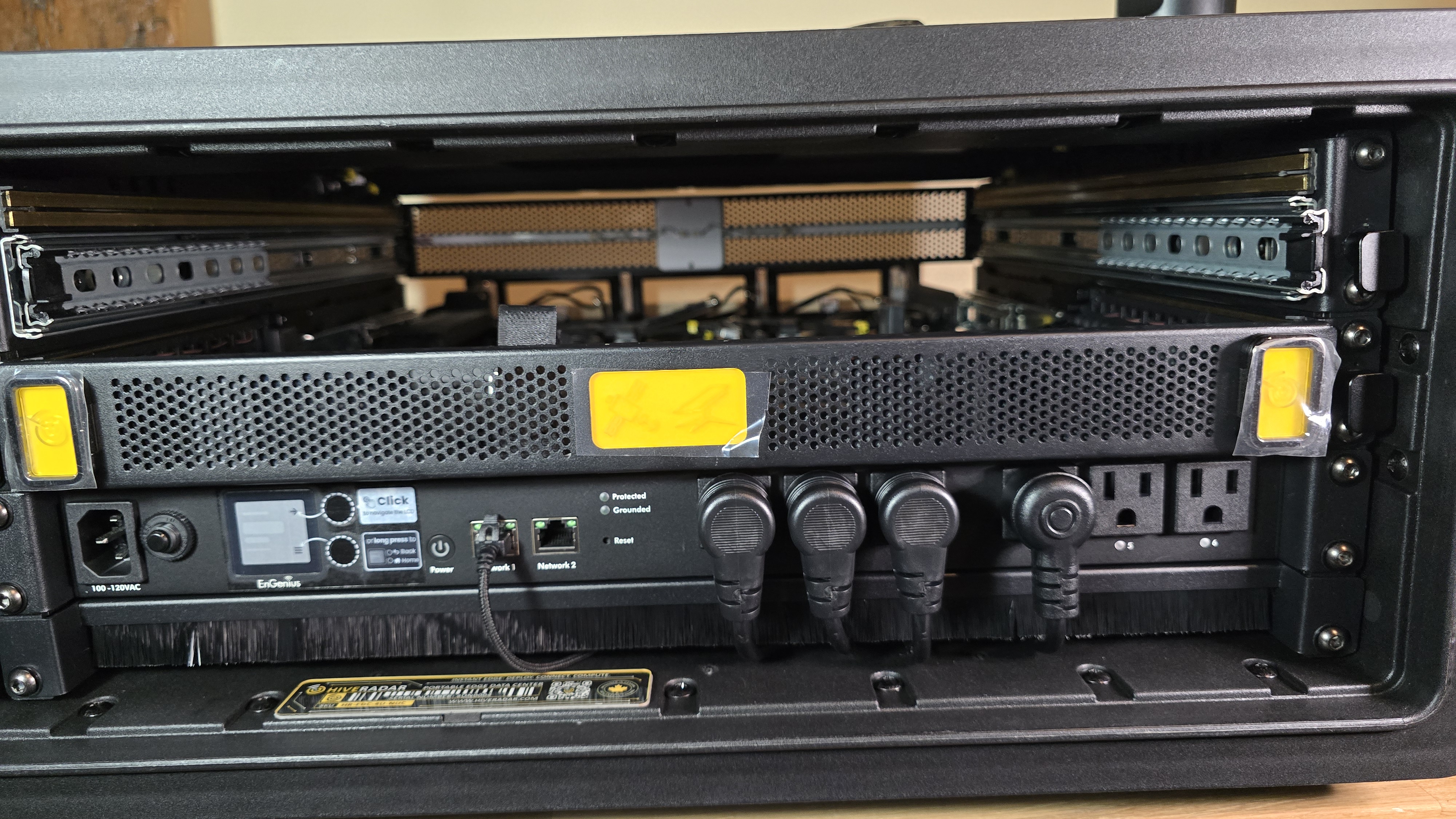
1.4: Mount Power Supplies
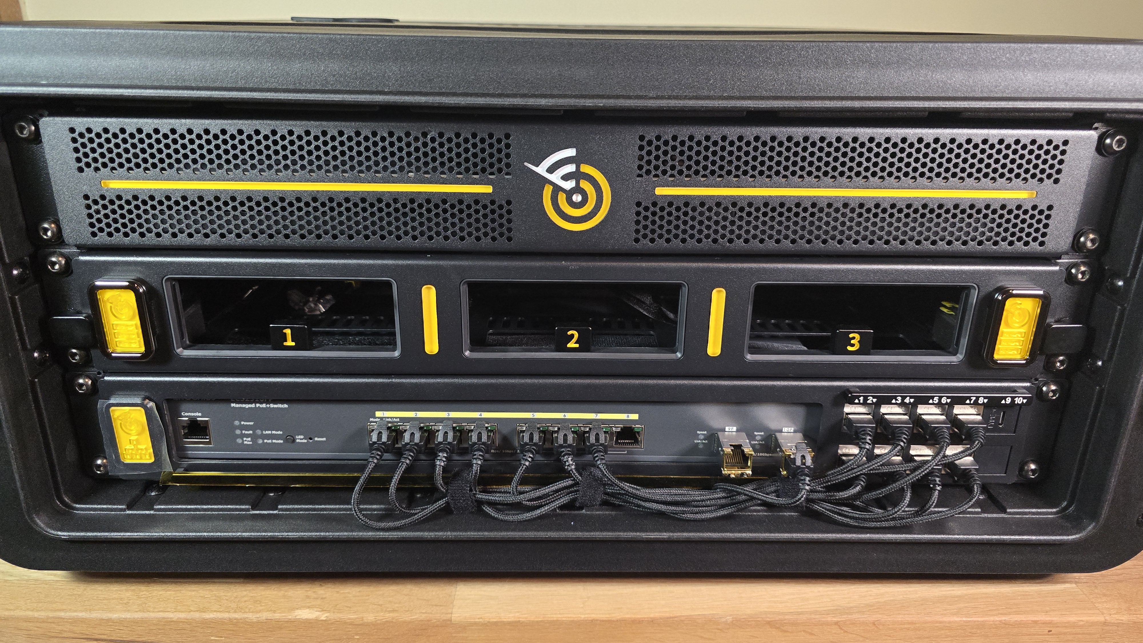
- Identify PSU mounting panel
- The PSU shelf is visible behind where the PDU was mounted (as per image below)
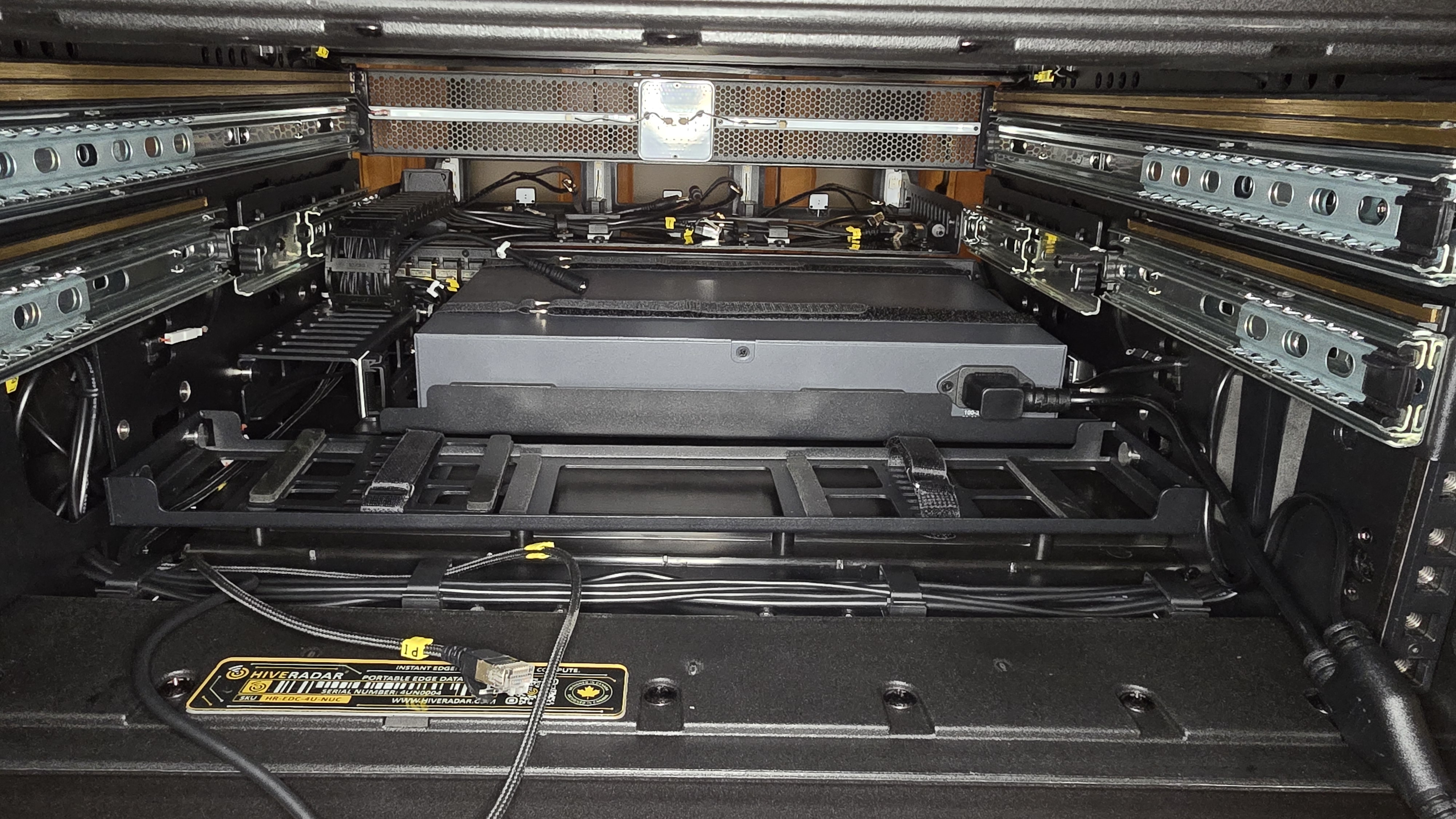
- Locate the NUC power input connectors on the left side of the switch
- These are where the PSU DC output cables will connect later
-
Slide out the PSU mounting panel
- By pulling the panel laterally towards yourself, slide the PSU mounting panel out without using much force
- Place it on a surface outside of the EDC
- Note: The PSU mounting panel is aligned to the guide knobs on each side; make sure to pull directly outwards toward yourself, no up or down movement is required
- Please note that the power cable leading to the switch may need to be disconnected before the panel can be removed
-
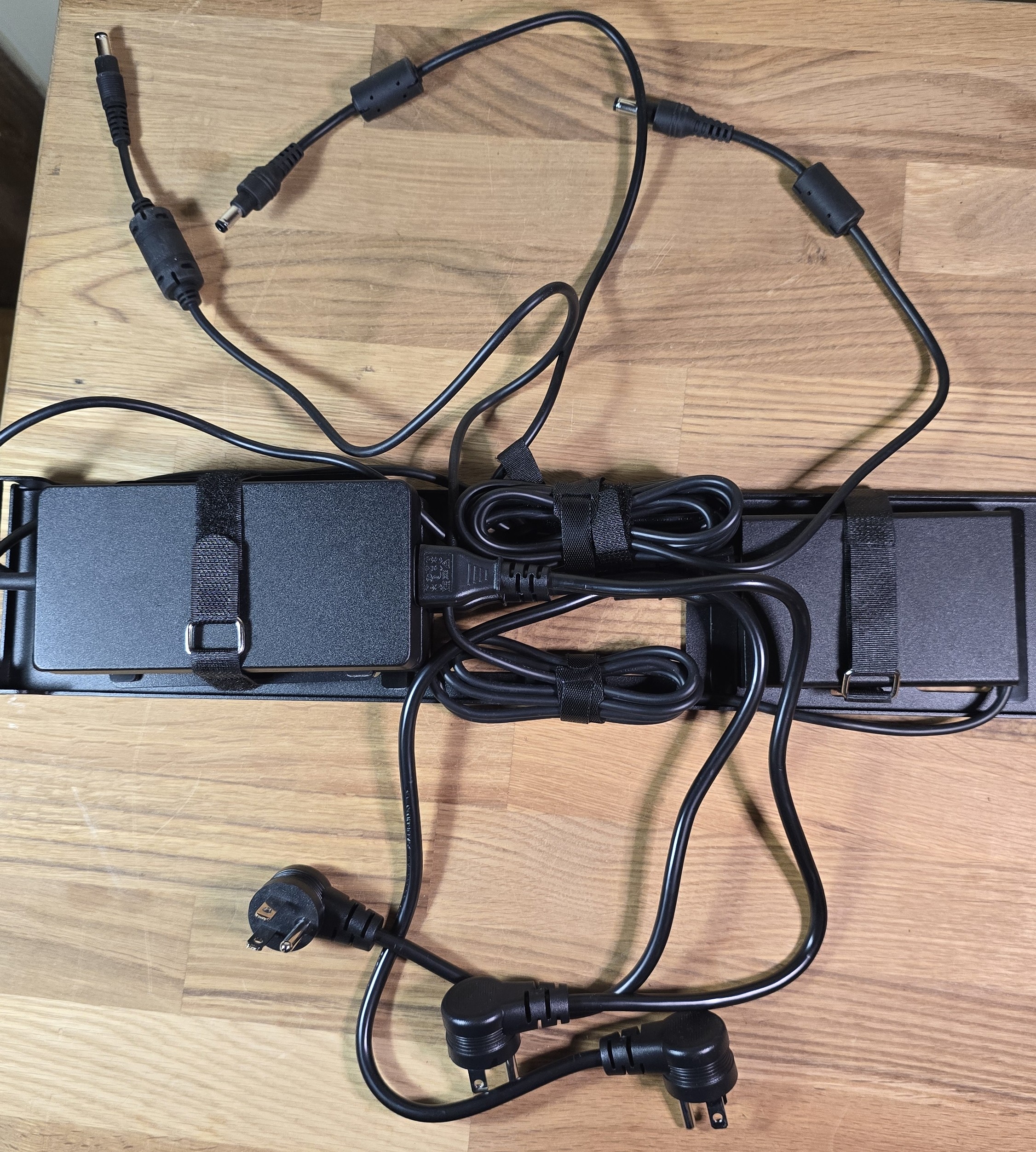
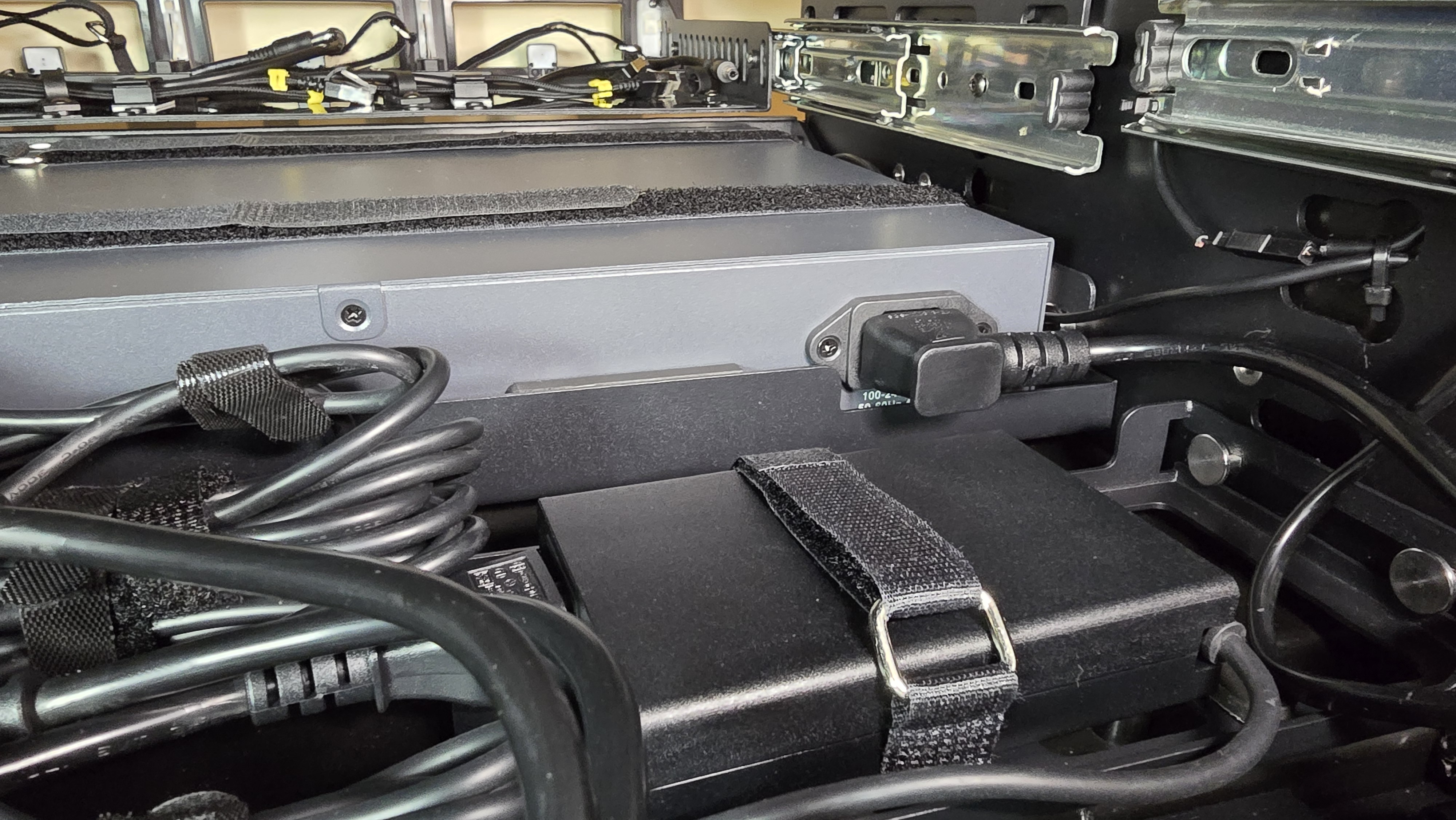
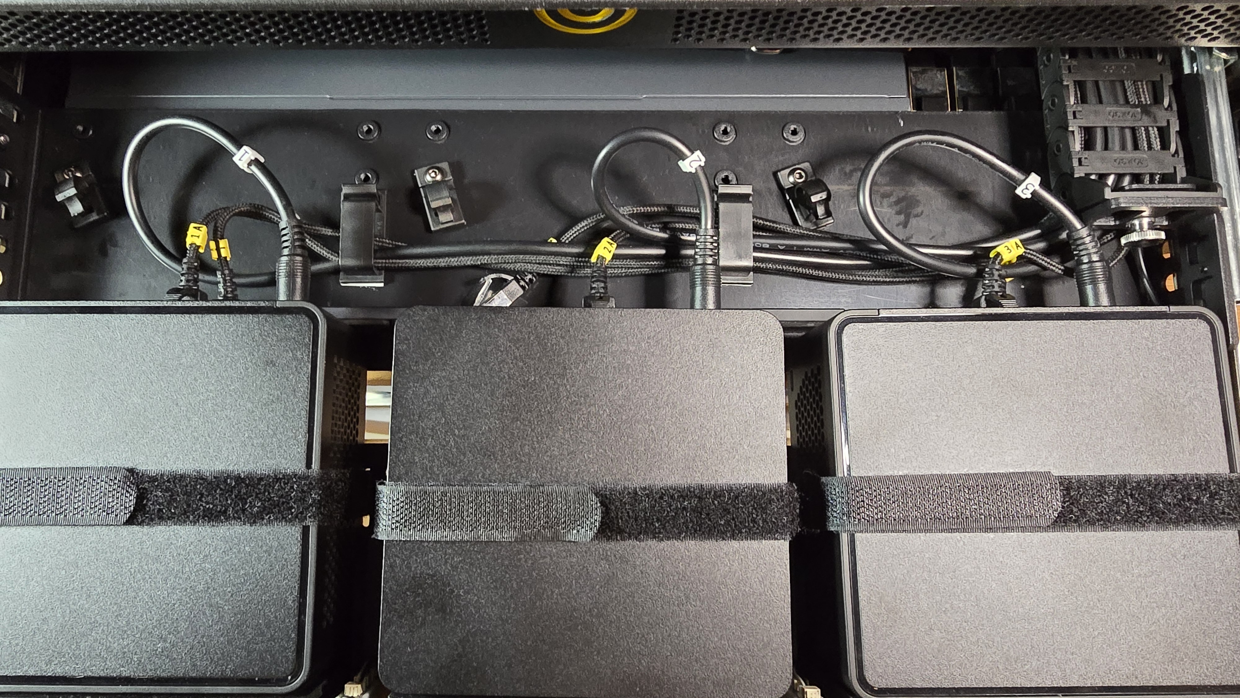
Prepare and secure the PSUs to the shelf
- Place the items that you will need: the PSU mounting panel, PSU spacer, 3 PSU units (without the plug from C5 to the wall outlet), 3 right-angle C5 to PDU cables, and additional velcro straps
- Placement:
- Place the first PSU on the shelf
- Place the second PSU on the shelf beside the first PSU
- Stack the third PSU on top of one of the first two PSUs, placing the PSU spacer between them
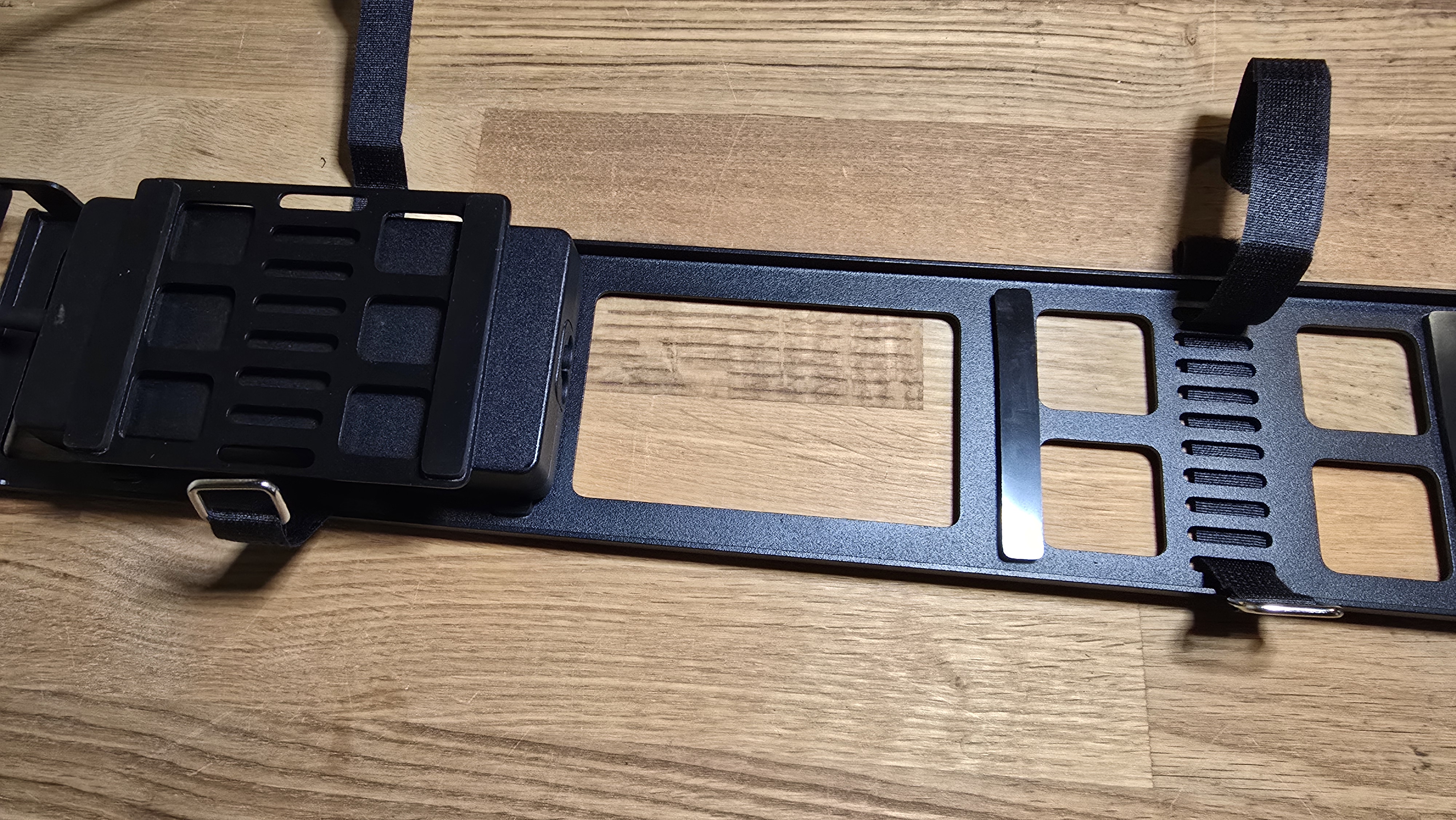
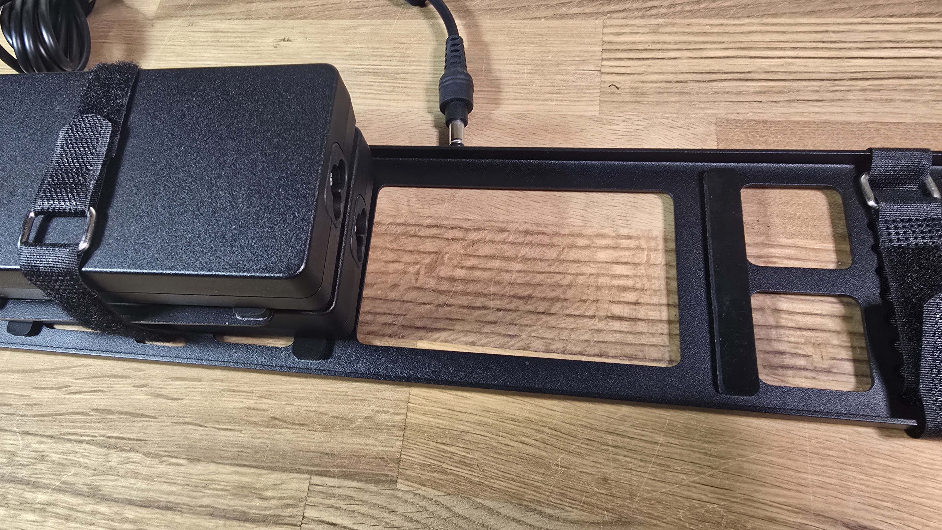
- Orientation: Ensure the C5 plugs on the PSUs face toward the middle of the panel to allow space for the cable routing
- Secure: Use velcro straps to secure each PSU to the shelf so they are stable and cannot shift during operation
-
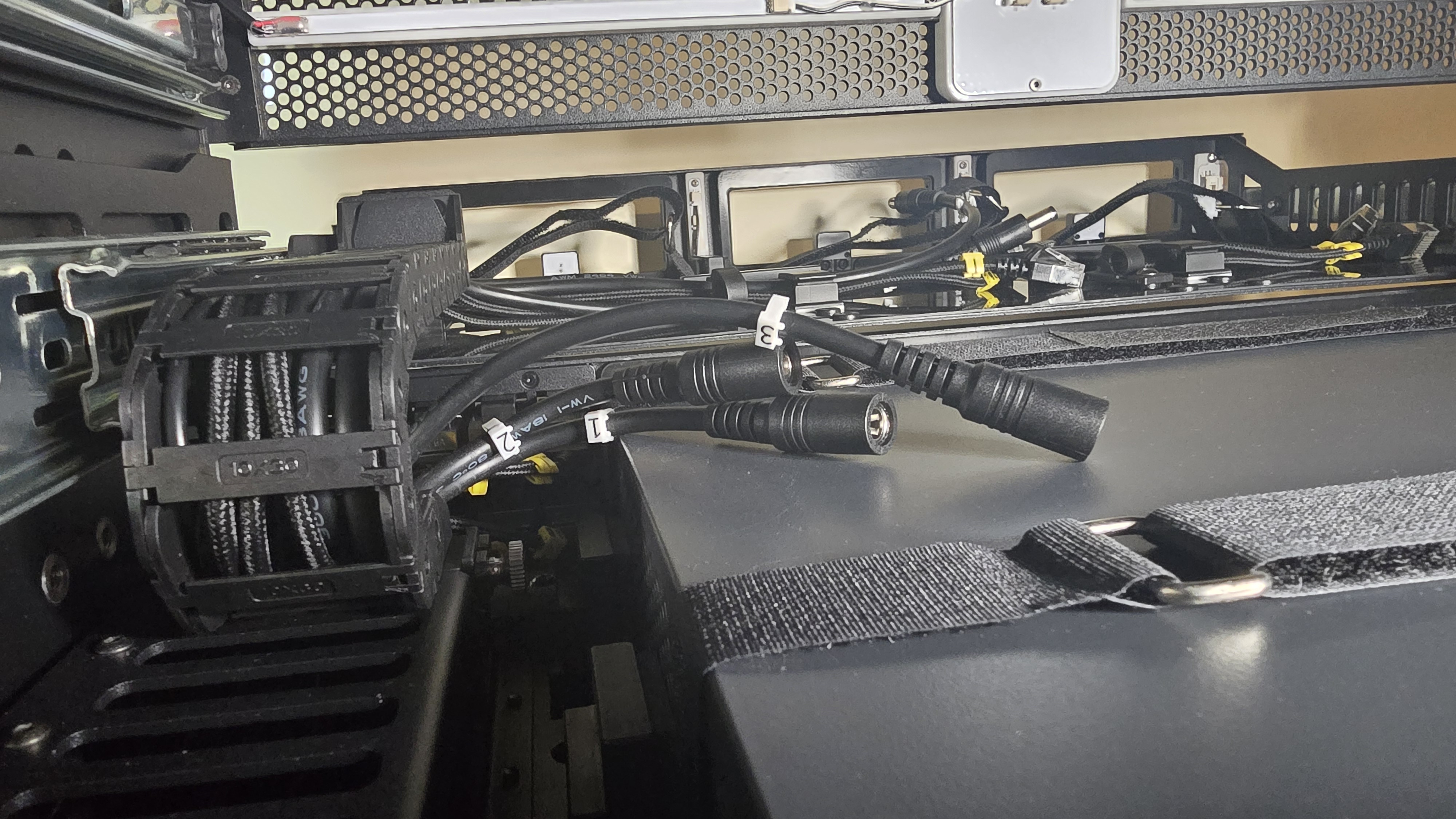
Connect AC power cables and label for consistency
- Locate the C5-to-PDU power cables (these have a standard C5 connector on one end and a right-angle plug on the other)
- Connect the standard C5 end into the AC input of each PSU
- Note: The right-angle plug end remains disconnected for now; it will be connected to the PDU in a later step
- Maintain Numbering Consistency:
- Identify which PSU will serve Node 1, Node 2, and Node 3
- It is highly recommended that the AC cable for the Node 1 PSU is eventually plugged into PDU Outlet 1 (and respectively for 2 and 3)
- Tip: It is recommended to label the loose right-angle end of each AC cable now (e.g., "1", "2", "3") to ensure they match their corresponding Node/PSU later
- Use velcro to secure excess cabling. Important: Ensure you leave sufficient slack in the DC output cables so they can comfortably reach the power input connectors on the left of the switch without tension.
-
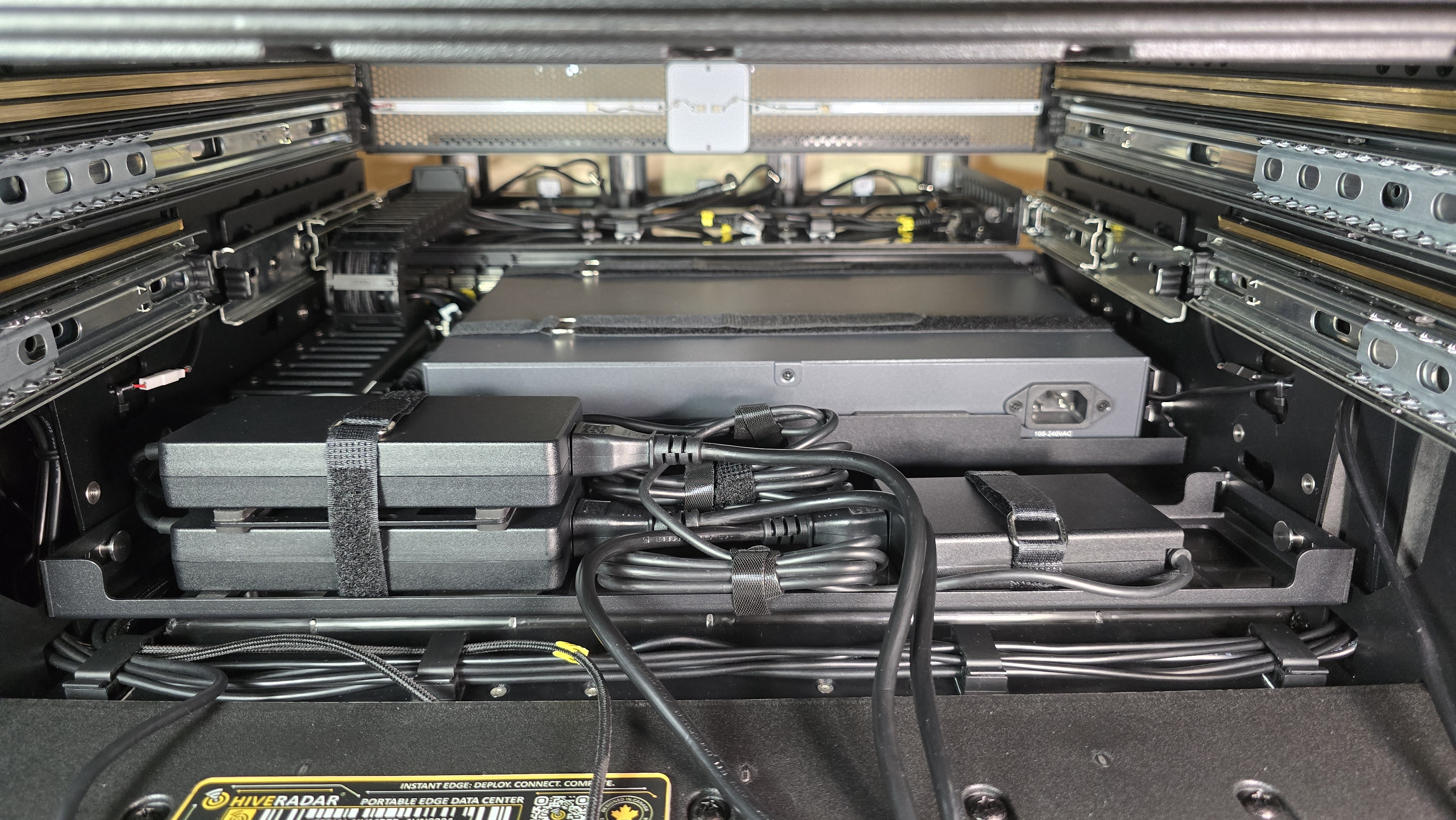
Re-install panel and connect DC output
-
Slide the populated PSU panel back into the EDC, using the guide knobs on each side as anchors
-
Connect DC Output:
- Connect the DC output cable (barrel connector) from each PSU to the labeled connectors on the left of the switch
- Ensure the mapping is preserved:
- PSU 1 (AC Cable "1") → Input Connector 1 (Node 1)
- PSU 2 (AC Cable "2") → Input Connector 2 (Node 2)
- PSU 3 (AC Cable "3") → Input Connector 3 (Node 3)
-
Using the clip to the left side of the back of the switch, secure the power cables for cable management
-
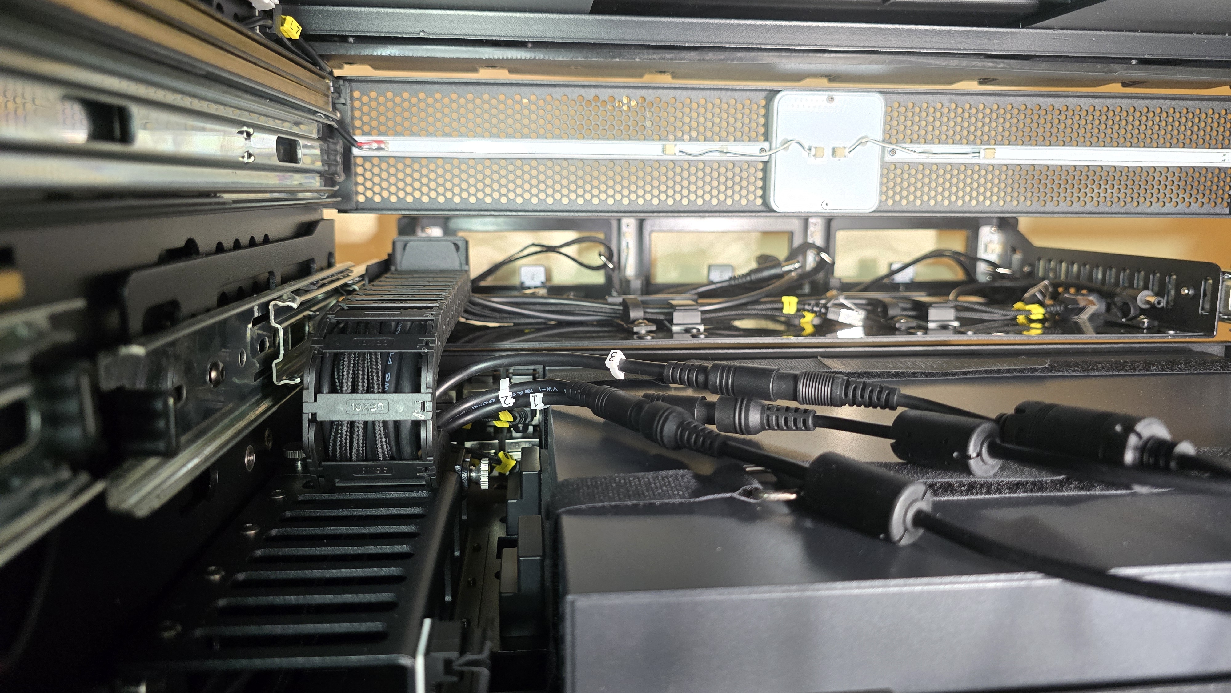
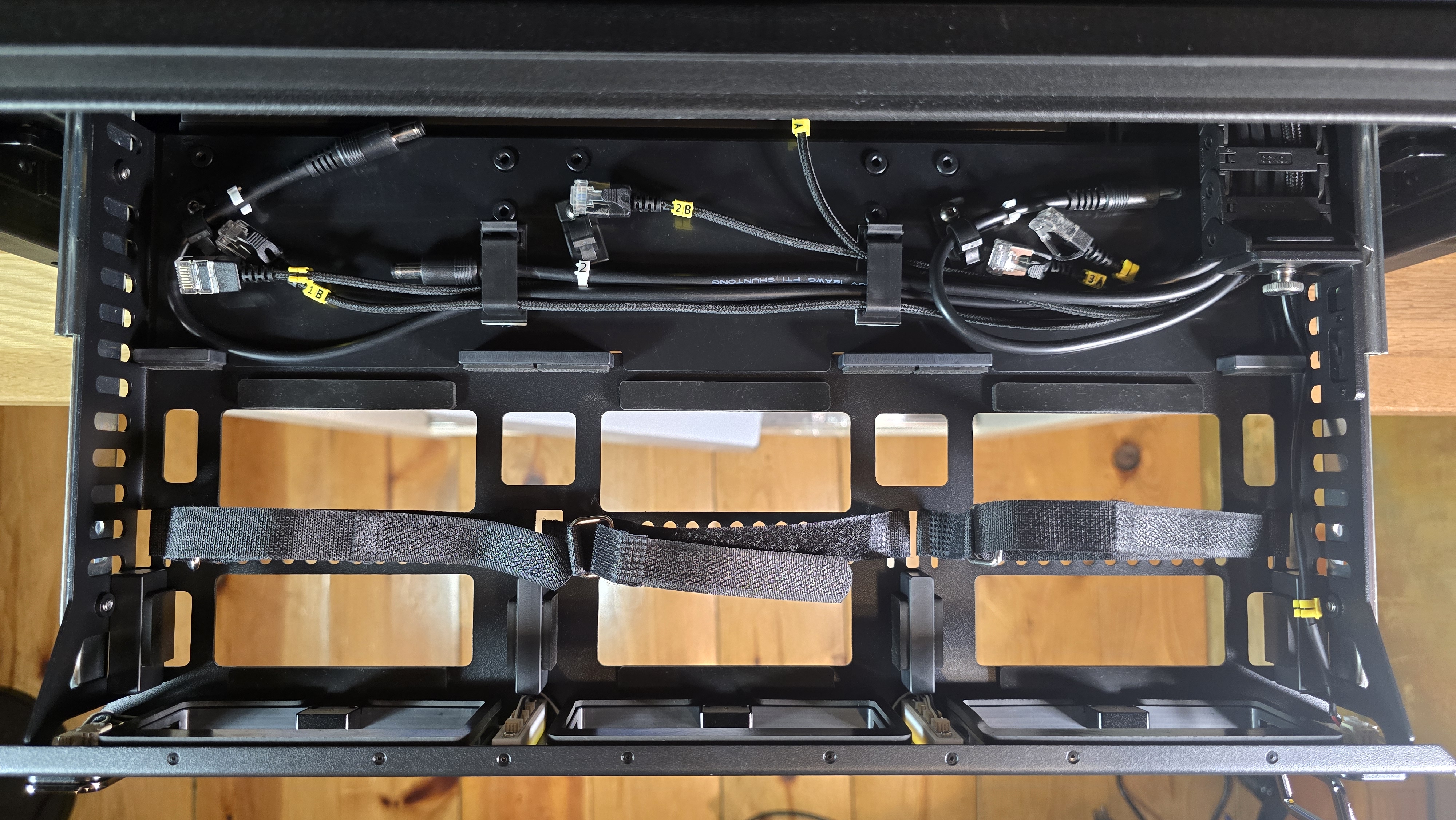
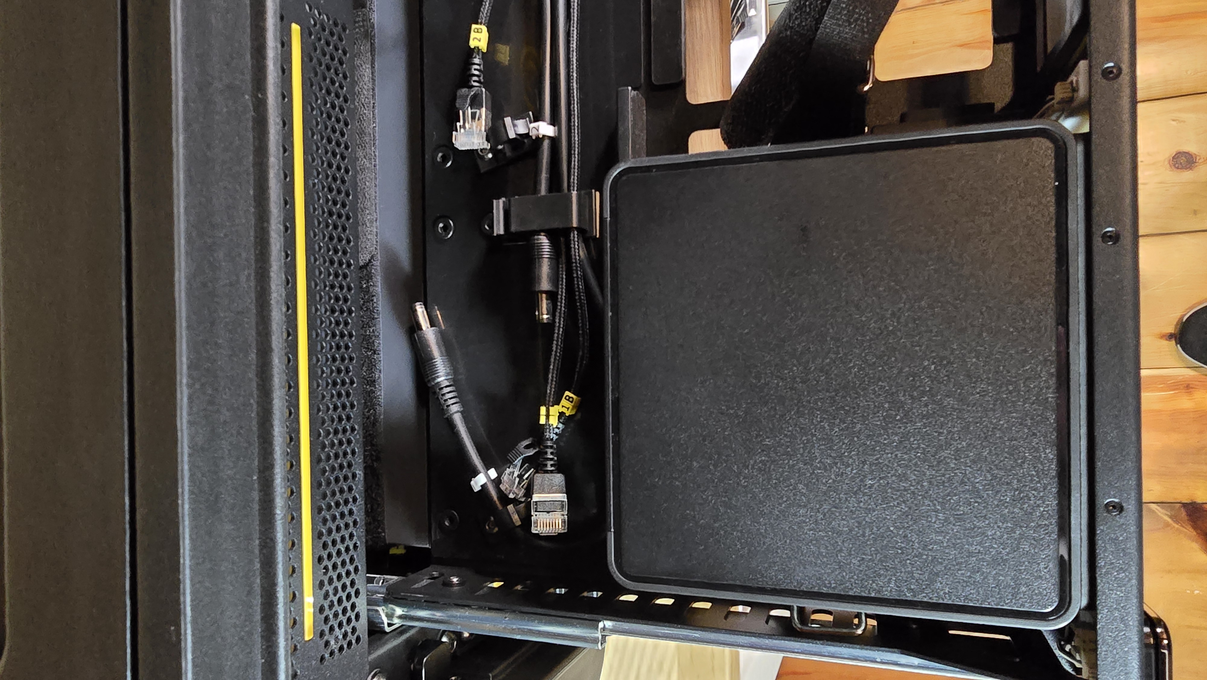
1.5: Route Cables Through Brush Panel
-
Prepare brush panel and connect IoT cables
- Position the brush panel near its mounting location (do not screw in yet)
- Locate the IoT device mounted underneath the brush panel
- Reconnect the Ethernet and USB cables to the IoT device
- Note: It does not matter which USB port is used; feel free to connect to any available port
-
Route power cables through brush panel
- Ensure the Switch power cable is connected to the switch power input (if it was removed previously)
- Route the 3× PSU right-angle power cables, the 1× Switch power cable, and the Ethernet cable labeled PDU through the brush panel openings
- Use minimal slack—pull just enough cable through to reach the PDU outlets comfortably
- Ensure the Switch power cable is connected to the switch power input (if it was removed previously)
-
Secure the brush panel
- Use a 4mm hex key
- Reinstall the 2× hex bolts on the sides of the brush panel (1 per side)
- Tighten securely
1.6: Reinstall PDU and Connect Power
-
Position PDU back on mounting rails
- Align the PDU with the mounting rail holes
-
Secure the PDU
- Use a 4mm hex key
- Reinstall the 4× hex bolts on the sides of the PDU (2 per side)
- Tighten securely
-
Connect the cables to PDU outlets
- Reconnect the Ethernet cable labeled "PDU" to the port labeled 'Network 1' on the PDU
- Connect the power cables to the outlets following the recommended assignment:
- Outlet 1: Node 1 power cable
- Outlet 2: Node 2 power cable
- Outlet 3: Node 3 power cable
- Outlet 4: Switch power cable
- Outlet 5: (Available for additional devices)
- Outlet 6: (Available for additional devices)
- Verification: If cables were labeled in previous steps, verify that the labels (1, 2, 3) match the PDU outlet numbers
- Try pushing any remaining cable slack under the brush panel
1.7: Reinstall Storage Drawers
- Reinstall middle drawer (short-depth drawer)
- Align drawer with rails on both sides
- Slide drawer onto rails carefully
- Push drawer in until it clicks and seats properly
- Verify smooth sliding operation
- Reinstall top drawer (full-depth drawer)
- Repeat same process for top drawer
- Align with rails, slide on, push until seated
- Verify smooth operation
- Test drawer function
- Pull each drawer fully out and push back in
- Drawers should operate smoothly without excessive force
- Note: Remember to secure the drawers with the twist locks when not used.
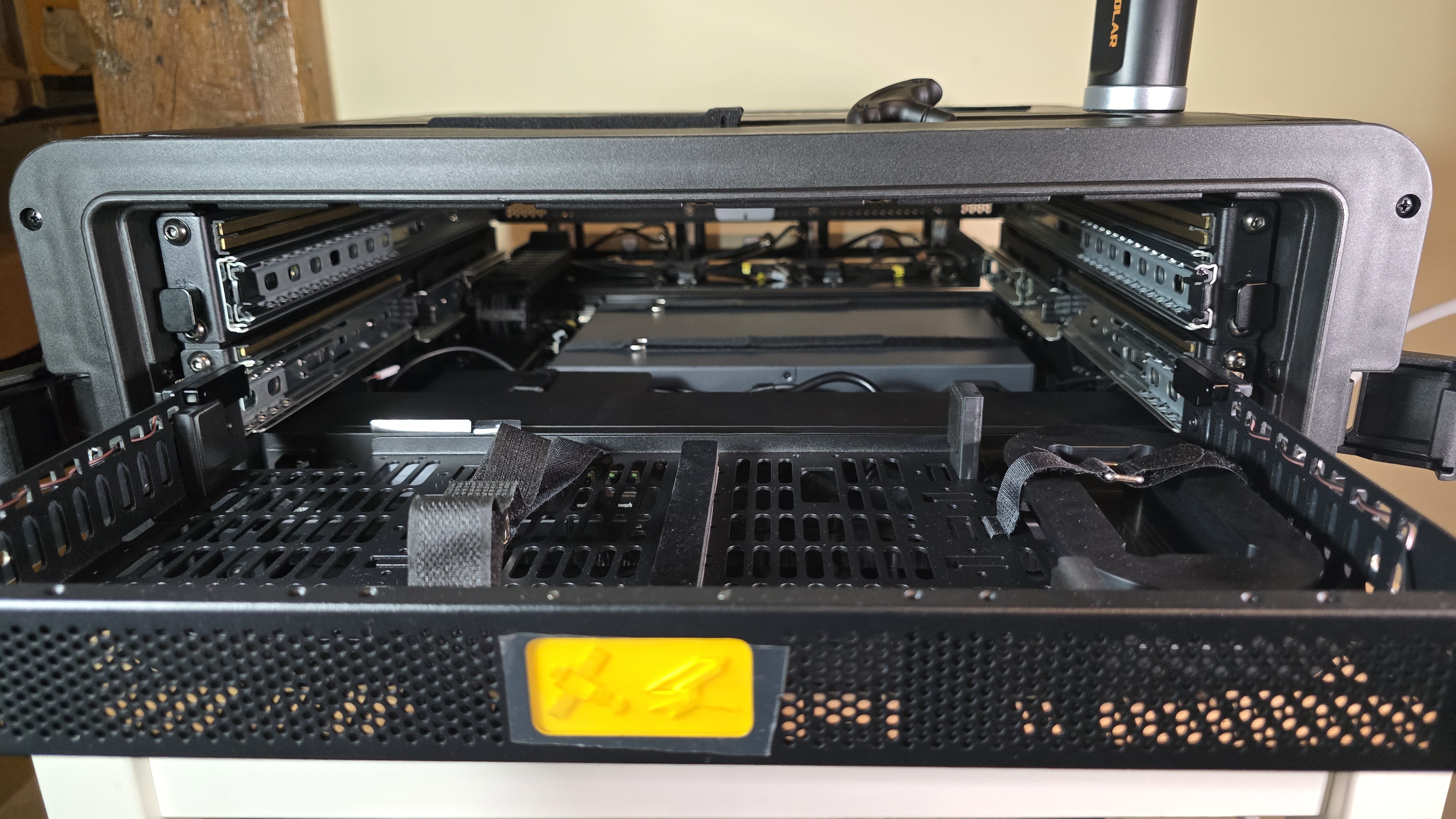
Step 2: Access the Compute Drawer to Install the NUCs
1 Remove front lid if not already removed
- Release latches on both sides
- Support lid weight while removing
- Set lid aside safely
- Locate the compute drawer
- Center drawer with backlit interior
- Labeled bays: 1, 2, 3
-
Unlock the compute drawer
- Locate locking mechanisms on left and right sides of drawer
- Twist both locks upwards to unlock position
-
Open the compute drawer
- Pull both fold-out handles to slide drawer out
- Drawer extends fully for access
Step 3: Install and Connect NUCs
Install NUCs one at a time in order: Bay 1, Bay 2, Bay 3
For Each NUC:
3.1 Prepare the bay
- Velcro straps are pre-attached to each bay
- Open/unfasten velcro straps to prepare for NUC placement
- Position NUC in bay (do not secure yet)
- Align NUC with the bay in the drawer
- Orient NUC with I/O ports facing backwards (toward the EDC core)
- Lower NUC onto bay, ensuring it sits flat
- Leave unsecured for easier cable access
-
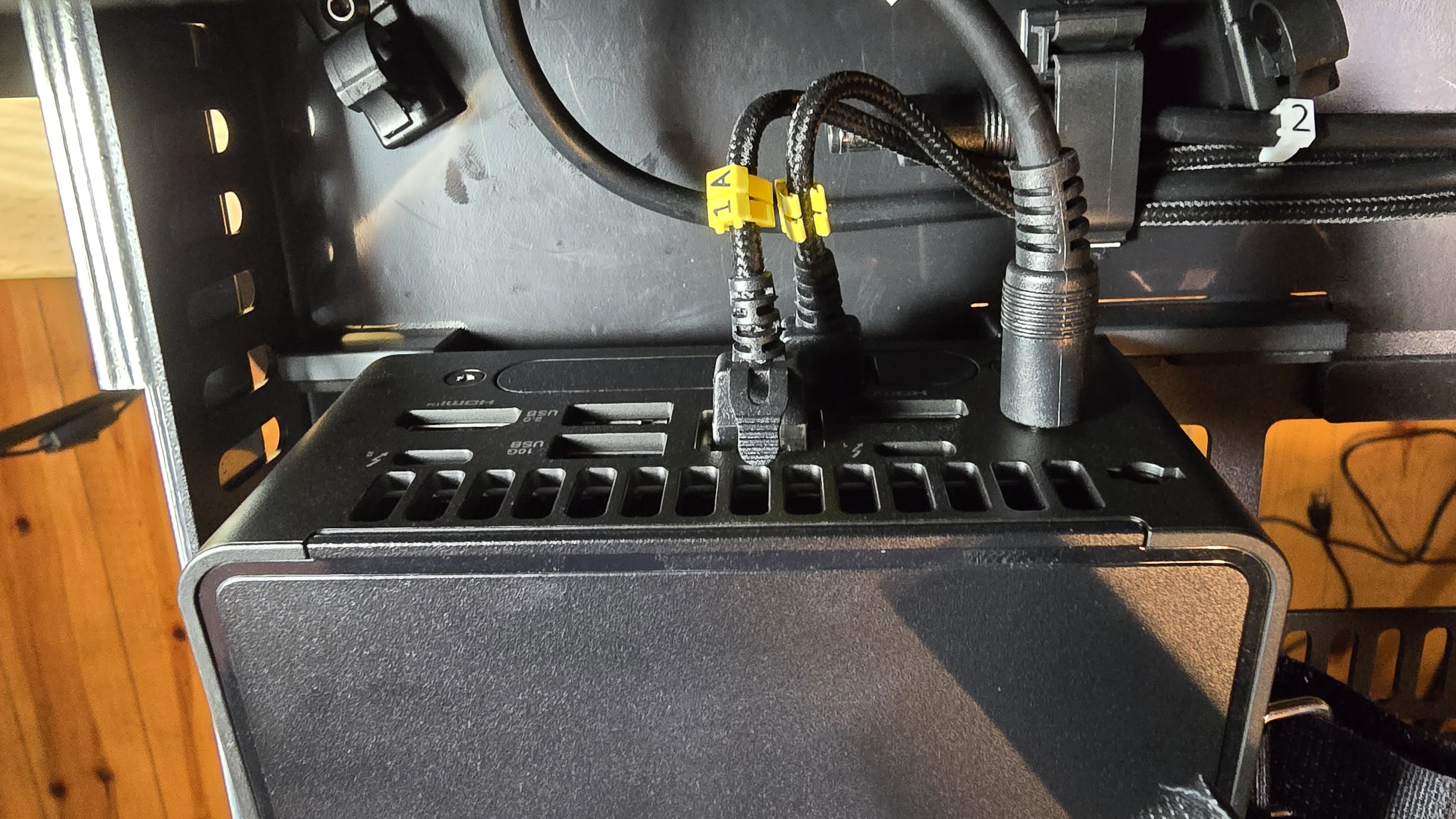
Locate pre-wired cables behind the NUC
- 1× power cable (labeled with node number: Node 1, Node 2, or Node 3)
- 2× network cables (labeled Node [number] A and B)
-
Connect network cables to NUC
- For NUC PRO with dual ethernet ports (expansion port):
- Cable A → Top ethernet port
- Cable B → Bottom ethernet port
- For NUC PRO with single ethernet port:
- Cable A → Ethernet port (recommended)
- Cable B → Leave disconnected (no second port)
- For NUC PRO with dual ethernet ports (expansion port):
-
Connect power cable to NUC
- Plug labeled power cable into NUC power input
- Ensure connection is firm and fully seated
- Leave the other end (PSU side) disconnected for now - will connect during PSU installation
-
Secure NUC with velcro straps
- Wrap velcro strap across top of NUC
- Fasten strap snugly to secure NUC in place
- Fold excess velcro strap back onto itself to prevent loose ends
- NUC should not move or rock when gently pushed
-
Repeat for remaining NUCs
- Install Bay 2, then Bay 3
- Verify labels match node numbers for each
Network diagram reference: See Network Port Reference for complete logical wiring diagram and keystone panel mapping.
Final Verification
After completing all installation steps:
Visual inspection:
- All 3 NUCs securely mounted in compute drawer bays
- All network cables (A and B) connected to NUCs (when applicable)
- All power cables connected from NUCs to PSUs
- All 3 PSUs securely mounted and optionally labeled
- PSU DC outputs connected to switch connectors
- PSU AC inputs connected to PDU outlets
- All drawers reinstalled and operating smoothly
- No loose cables or components
- PDU and brush panel securely mounted
Cable verification:
- Network cables properly routed and not pinched
- Power cables properly routed with adequate strain relief
- No cables obstructing airflow or moving parts
- All connections firm and fully seated
Workspace cleanup:
- 4mm hex key returned to top shelf storage compartment
- All tools and materials cleared from work area
- Removed drawers stored safely if not reinstalled
- ESD protection equipment properly stored
Recommendations
Documentation:
- Consider taking photos of final installation for future reference
- Record PSU labels and outlet assignments for troubleshooting
- Keep labeling consistent with network diagram
Before power-on:
- Review Power & Startup procedures
- Ensure all lids remain removed for operation (front and rear)
- Do not power on until ready to continue with configuration steps
What's Next?
After completing NUC installation:
👉 Power & Startup - Connect main power and perform first boot